|
|
Transfer Die Workflow
The Cimatron processes involved in creating a Transfer Die are detailed below:
![]()
-
Run the Transfer Die Setup Wizard and browse for a master part (final product). Only one master can be handled per project.
A default assembly tree with a predefined structure is created with two distinct environments - the Process Design environment and the Tool Design environment.
![]()
The Die Transfer Forming Shape Guide is displayed.
-
Within the Process Design environment, first create intermediate shapes using the Forming Shape function (this is no different than Progressive Die). This includes creating the forming shapes that will be included in the process. These forming shapes are generally copies of parts originating from the master die design file, that are changed using the bend, unfold, unbend and blanking operations.
![]()
-
If required, you can then add a 2nd row of forming shapes using the Add 2nd Row function. Added forming shapes may be mirrored or not.
![]()
-
You can now plan the piercing sequence (which holes will be created at which station) using the Piercing Design function (this function is also applicable for Progressive Die).
Piercing design is used for parts having arrays of holes that must be pierced in several consecutive operations, such as parts used in the electronic and computer industries.
-
You now switch to the Tool Design environment by clicking the Switch to Tool Design button at the bottom of the Forming Shape Guide.
-
Within the Tool Design environment, define the progression value, the number of stations and the die sets arrangement, by using the Die Sets / Station Settings function. The output of this function is a number of sub-assemblies that are used later in tool design. Each sub-assembly corresponds to a suitable die set, incorporating one or more stations.
![]()
-
Use Forming Shapes > Add to Die Set function to add forming shapes to the appropriate tool sub-assemblies, so that eventually, the previously created sub-assemblies will contain one or more forming shapes (this is analogous to the Add to Strip function in Progressive Die).
![]()
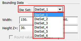
Note: The Setup in Transfer Dies enables you to define different setups for each sub-assembly of the tool design. The Die Set dropdown list option appears in the Setup dialog in the General tab and also in the Strip Layout tab (in the Bounding Data area); this dropdown list option is only displayed for Transfer Dies. The example below shows the dropdown list in the Strip Layout tab of the Setup dialog.
|