|
|
Setup – Strip Layout / Punch Tabs: Die Project 
![]()
![]()
Access: Open this function from one of the following locations:
-
Select Tools > Main Tools > Setup from the menu bar.
-
Select Die Design > Tools > Setup from the menu bar.
-
Select Mold Design > Tools > Setup from the menu bar.
-
Select Setup from the Mold Design Guide Toolbar, Parting Guide Toolbar or one of the various Die Design Guide Toolbars).
Setup parameters are those that are significant for various aspects of a project design. They represent geometrical features of the model being designed as well as parameters that influence that design. Each parameter can be assigned a value, and the dimension related to this parameter is updated accordingly. These parameters are displayed in a Setup dialog.
The Setup dialog table displays the entire set of data used in the setup of a Part or Assembly project; these parameters are used in the Part and Assembly environments (assembly includes all assembly projects – plain Assembly, Mold, and Die projects).
See Tabs usage for which tabs in the Setup dialog are relevant for each type of project.
The table of user-defined parameters is available in the General tab of the Setup dialog. Use this table to predefine various parameters used for creating relations.
See Setup dialog description for more on the common elements in all the tabs.
Tabs in the Setup dialog
- General - Part/Assembly
- Strip Layout - Die projects
- Punch - Die projects
- Mold Layout - Mold projects
Defining the Die Setup parameters
-
Load the Die file and view the Die Setup.
-
InvokeInvoke the Die Setup function.
-
Set the parameters in the Strip Layout tab and Punch tab using this section as a guide.
Strip Layout tab
This tab contains Forming, Progressive Die Nesting, and Bounding Data parameters. The Bounding Data parameters are derived from the workpiece size, and most of them are dimmed (read only) if a workpiece has been defined.
|
|
Define the following parameters:
|
||||

Transfer Dies
For Transfer Dies, a Die Set dropdown list is displayed in the Bounding Data area of the dialog. This lists all the Die Sets created and is used to define different setups for each sub-assembly of the tool design (see the images below). This list is also displayed in the General Tab of the dialog.
![]()
![]()
![]()
Note: A dimension in a Transfer Die that belongs to one DieSet cannot be linked (in a formula) to a setup dimension from another DieSet. The Die Set dropdown list (in the Setup dialog > Strip Layout tab) displays the die set to which the dimension belongs and is dimmed (cannot be edited).
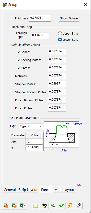
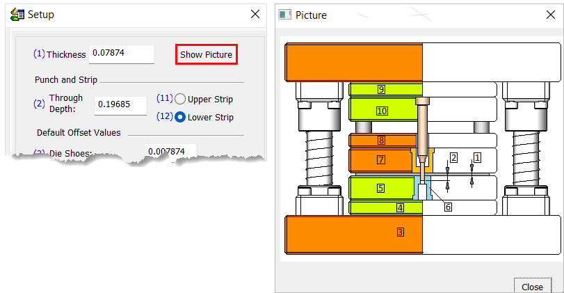
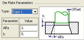
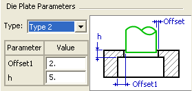
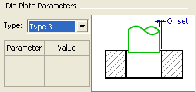
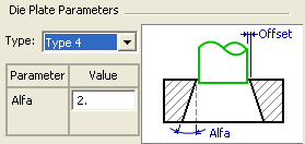
Punch tab
This image shows the Punch tab.
|
|
Define the following parameters:
The numbers in the Trimming Punch preview correspond to the numbers in the Die Setup dialog (as shown above).
Note: The Default Offset Values can be overridden using the Load Setup dialog. See Load Setup button.
|
|