Chamfer  : Options and Results


Access: Open this function from one of the following locations:
-
Click
in the toolbar. -
Select Solid > Main Tools > Chamfer from the menu bar.
-
Select Chamfer on the popup menu when no geometry is selected.
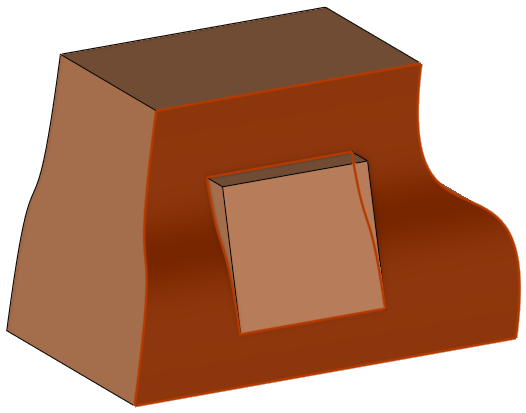
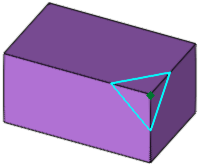
Create a chamfer on a sharp corner.
Select edges and/or vertices, or a face to create a chamfer. When selecting multiple edges, different chamfer angles can be defined for each edge.
Required Step 1 
PickPick edges and/or vertices (end points), or a face. Set the parameter.
-
You can select an edge by picking a point that lies on the edge.
-
You can drag a box to select multiple edges.
-
Edges and vertices can be selected in combination, but only one face can be selected.
|
Face selection |
Edge selection |
Vertex selection |
|
|
|
|
|
|
Face selection
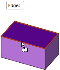
When picking a face (Edges option):
-
First, select the Enable/Disable selection of Faces icon in the Filters Toolbar.

-
Select only one face (that is not a round or an open solid face).
-
The following faces can be selected:
Simple Face
Face with internal cut
Nurb face
Nurb face with internal contour
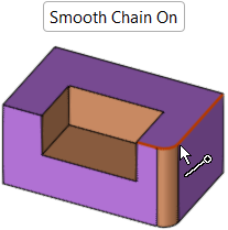
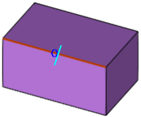
Edge selection
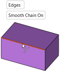
When picking edges (Edges option):
-
You can select an edge by picking a point that lies on the edge.
-
You can pick By Box to select multiple edges.
-
Edges and vertices can be selected in combination. When a vertex is picked, the edges of the vertex are marked as selected.
|
Edge Selection - |
Edge Selection - |
|
|
|
|
Vertex for Edge Selection - |
Vertex for Edge Selection - |
|
|
|
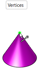
Vertex selection
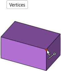
When picking vertices (Vertices option):
-
Only the end points of a solid body can be selected.
-
Only vertices whose adjacent edges are stitched (no free edges) can be selected.
-
Vertex selection is ignored in cases where the result is added material on a concave and convex chamfer on the same vertex.
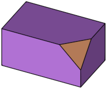
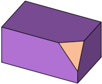
ExampleExample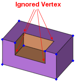
When you are finished selecting, press exitexit.
Required Step 2 
All selected edges/vertices are marked with a preview symbol that reflects the size of the given chamfer (as set by a Distance parameter - see below). Each selected edge/vertex is also marked with a symbol that enables you to set a different chamfer value for a specific edge.
| Chamfer Edge preview | Chamfer Vertex preview | |||
|
|
|
|
|
|
The parameters that are displayed depend upon the chamfer option selected from the dropdown list:
| Chamfer Edge parameters | Chamfer Vertex parameters | ||||
|
|
|
|
|
|
|
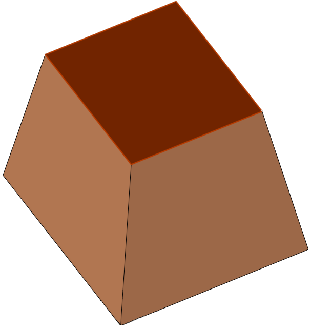
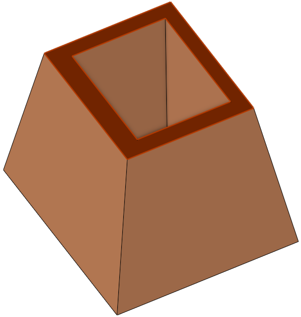
Chamfer Vertex parameters
The following types of chamfers can be created on vertices.
|
|
|
|
|
|
|
|
Parameters
|
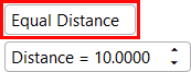
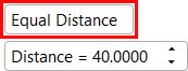
Equal Distance / |
Toggle option to define the distance from the vertex where the chamfer is to be created.
|
||||
|
Distance |
Set the distance from the vertex along its edges that the chamfer is created. The default distance is 10 mm (0.5 inch). |
Notes:
-
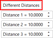
If the number of edges for each selected vertex = 3, the Equal Distance / Different Distances parameter options are available.
-
If the number of edges for each selected vertex ≠ 3, only the Equal Distance parameter option is available (it is displayed grayed out).
-
If the number of edges for some of the selected vertices = 3 and others ≠ 3, and if the Different Distances parameter option is selected, the vertices whose number of edges ≠ 3 are created according to the Distance 1 value (the Different Distances and Distance 1 parameter texts are displayed in blue to signify this).
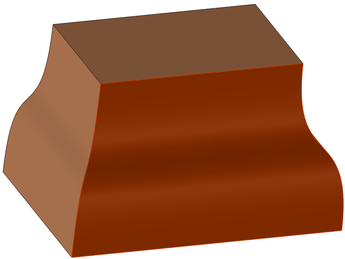
Chamfer Edge parameters
The following types of chamfers can be created on edges.
|
|
|
|
|
|
|
|
|
|
|
|
Parameters
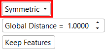
|
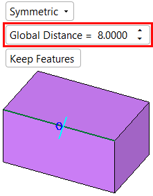
Symmetric |
This is a dropdown list containing the following options:
|
||||||||||||||||||
|
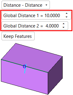
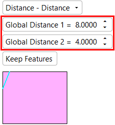
Enter the desired chamfer distance (or depth). The value you enter is the horizontal and vertical dimension of the chamfer, as shown below:
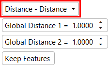
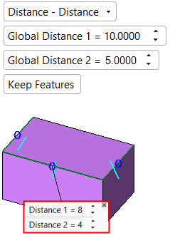
In the chamfer option Distance - Distance, the Global Distance parameter can be defined for each side of the selected edge.
To set local values for a specific edge, see Local Parameter Values below. |
|||||||||||||||||||
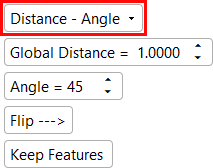
|
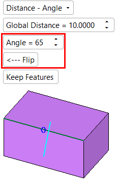
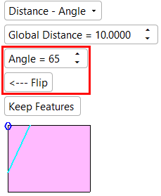
Angle |
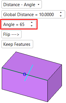
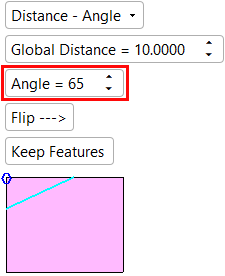
Enter the desired chamfer angle. This parameter is only displayed if the Distance - Angle toggle option is selected above.
Note: If the corner angle on which the Chamfer function is performed is not a 90 degree angle, then the input angle will be calculated for the first corner edge in the chamfer chain (providing the Chamfer function is performed on more than one edge). The calculated angles of the other edges (containing corner angles that are not equal to the first corner angle) will not be calculated as the input angles. |
||||||||||||||||||
|
Flip |
The Flip --> / <-- Flip toggle option flips the direction of the defined Angle along the selected edges. This parameter is only displayed if the Distance - Angle toggle option is selected above.
|
||||||||||||||||||
|
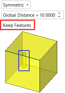
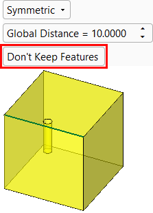
Keep Features |
This is a toggle option Keep Features / Don't Keep Features.
|
||||||||||||||||||
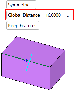
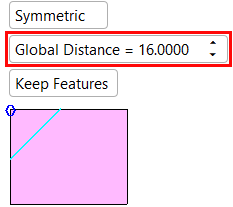

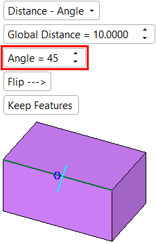
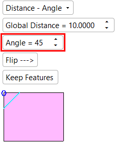
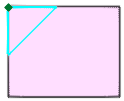
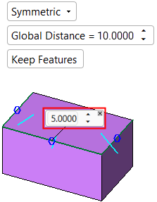
To set local values for a specific edge, click the blue circle on the appropriate edge to display a parameter label. Set the specific local value(s) for this edge in the displayed label, as shown in the example below. Different values for multiple edges can be set in this way.
ExampleExample
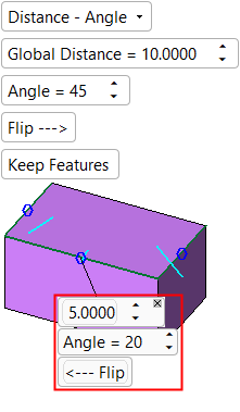
The parameters displayed in the local labels (highlighted below in red) depend on the dropdown list option selected above.
|
Symmetric |
Distance - Angle |
Distance - Distance |
|
|
|
|
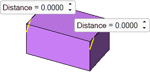
Optional Step 1 
Set the chamfer stopped distance value for chamfers on edges. This optional step is not available for chamfers on vertices.
The stopped distance is used to stop the chamfer at a set distance from one or both ends of the entity selected in required step 1. If the chamfer is to be stopped at both ends, different stopped distance values can be set for each end.
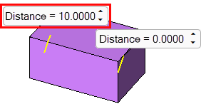
|
Distance parameters are displayed at both ends of the chamfer. |
Set the required stop distance. |
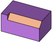
The chamfer is produced up to the stop distance. |
|
|
|
|
Press exitexit when finished. Click OK ![]() or Apply
or Apply ![]() in the Feature Guide to complete the function.
in the Feature Guide to complete the function.
When completed, the Chamfer feature will appear in the Feature Tree.