Offset Along Faces  : Options and Results


Access: Open this function from the following location:
-
Select Wireframe > Main Tools > Offset Along Faces from the menu bar.
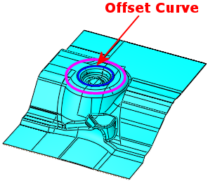
Offset a curve along 3D faces (or mesh) so that the offset value is kept along the selected faces.
This is useful for parting surface splitting at a certain distance from the parting line, as well as for similar operations in die design.
Required Step 1 
-
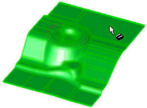
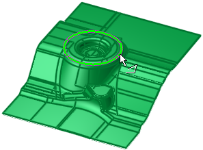
Pick the reference object (B-rep or mesh) along which the curve is to be offset.
Reference object
Object selected (colored GREEN)
Required Step 2 
-
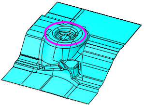
Pick the curve to be offset and set the parameters.
-
Pick a wire or curve/edge lying on the selected object and set the parameters. This curve will be offset along the reference object selected in step 1.
Parameters
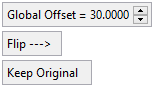
Global Offset
Set the distance the new geometry is to be offset from the reference geometry.
Default = 10 mm (0.5 inch).
The offset geometry lies on the reference object faces, where the distance is measured along the faces.
ExamplesExamples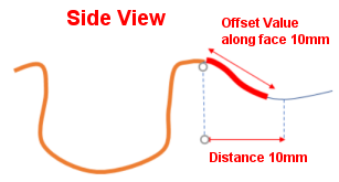

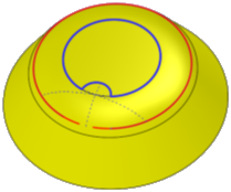
Flip
Toggle option to flip the resulting geometry to either side of the reference geometry.
The default offset side is outside for a closed reference contour and according to the curve direction for an open reference contour.
ExamplesExamplesOffset result
Offset result flipped side
Keep Original
Toggle option to either keep or remove the original geometry.
Note: Partial results may be obtained in some cases, for example, if the resulting geometry has intersecting curves.
-
Click OKOK
 or ApplyApply
 in the Feature Guide to complete the function.
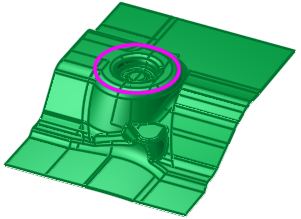
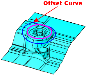
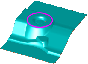
Cyan geometry to be offset
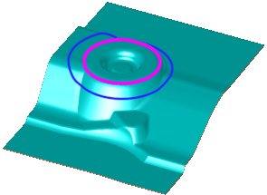
Result - blue geometry offset along faces
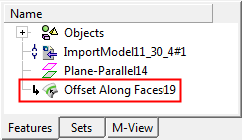
When completed, the Offset Along Faces feature will appear in the Feature Tree.