|
|
Shank and Holder Usage Dialog

Access: Open this function from the following location:
-
Click the Access button in the Shank and Holder Advanced branch of the Motion Parameters table.
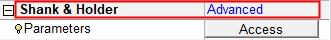
This displays the Shank and Holder Usage dialog.
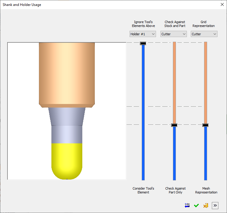
The Shank and Holder Usage dialog displays the default shank and holder parameter settings and enables you to adjust the parameters as required. A graphical interface and slider controls assist in explaining the parameters.
The Shank and Holder Usage dialog is initially displayed in collapsed mode, without showing parameter settings.
The dialog can be expanded to the right. The left side of the dialog controls the shank and holder usage (for procedure collision check calculations) and the right (expanded) side of the dialog deals with safety margin values, minimal clear length, and how the system deals with colliding motions.
|
|
Use the Expand See Collapsed for dialog items specific to this mode. See Expanded for dialog items specific to this mode. |
Use the Expand ![]() to expand the dialog to show all options.
to expand the dialog to show all options.
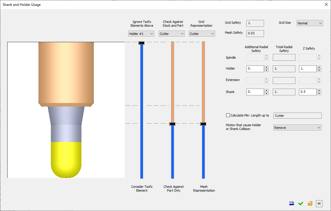
The availability of sliders and/or parameters in the Shank and Holder Usage dialog is procedure-dependent. The dialog images above show a general case for Finish procedures with a single cutter and no tilting. See Procedure-Dependent Shank and Holder Usage dialog for additional examples of the dialog.
See Collapsed for dialog items specific to this mode.
See Expanded for dialog items specific to this mode.
Dialog Buttons
The following buttons are in the dialog
|
|
Reset: Reset all values and settings to the system defaults. |
|
|
OK: Accept the changes, perform the operation, and close the current dialog/task. |
|
|
Cancel: Cancel all changes and close the dialog/task without saving the settings. |
|
|
Expand Expand/Collapse: Expand the dialog to show the Advanced options. Collapse the dialog to hide them. |
Procedure-Dependent Shank and Holder Usage Dialog
The available of sliders and/or parameters in the Shank and Holder Usage dialog is procedure-dependent. The dialog images above show a general case for Finish procedures with a single cutter and no tilting. Some additional cases are shown below.
Volume Milling > Rough Parallel/Rough Spiral
Volume Milling > Volumill Rough
Volume Milling > Rough Parallel/Rough Spiral
|
The following dialog status is displayed: The left and middle sliders are active and the right slider is irrelevant. The tool elements are always checked against the grid representation of the part and stock; therefore, the right slider is grayed out. If the middle slider handle is above the minimum (Cutter), the Calculate Minimum Length up to parameter is grayed out and its checkbox is turned OFF If the middle slider handle is at the minimum (Cutter), the Calculate Minimum Length up to parameter is available. When this checkbox is marked The Motion that cause Holder or Shank Collision parameter is not displayed. |
Example of Rough Parallel / Rough Spiral sliders and parameters |


Volume Milling > Volumill Rough
|
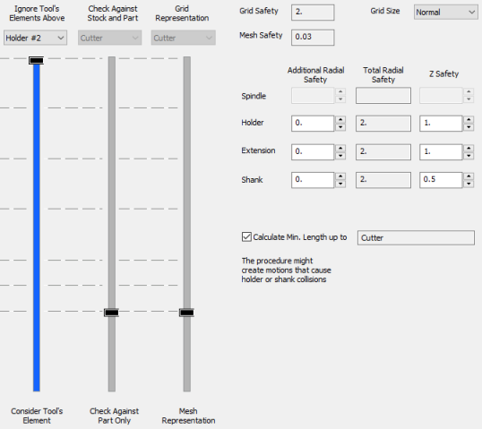
The following dialog status is displayed: The left slider is active and the middle and right sliders are locked to the bottom (Cutter). The Calculate Minimum Length up to parameter is available if a tool element other than Cutter exists and is active. The Motion that cause Holder or Shank Collision parameter is not displayed. |
Example of Volumill Rough sliders and parameters |
Multiple Cutters
|
The following dialog status is displayed: If all the cutters are topologically identical (they have the same list of element names), the first cutter is used to represent all the cutters. If all the cutters are not topologically identical: The slider ticks are displayed for the Cutter, Shank, Extension, Holder, and Spindle. Only those elements that exist in at least one tool are shown. The size (diameter and height) of each tool element are taken from the largest option. If more than one Shank or Holder or Spindle exists, they are referred to as single unit. The Calculate Minimum Length up to parameter is available only if the middle and right sliders are equal and if all tool elements below them (except the length of the last cutter) are identical. The Motion that cause Holder or Shank Collision parameter is available if the middle and right sliders are at their lowest position. Otherwise, the parameter is grayed out and locked to Remove and, in addition, the Calculate Minimum Length up to parameter is also grayed out and its checkbox is turned OFF |
Example of Multi Cutter sliders and parameters |

The display of the multi cutters in the dialog is as described in 2b and 2c above. This is illustrated below.
|
|
|
|
|
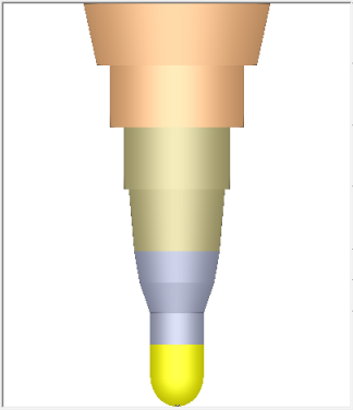
Display of Cutter 1 used in the procedure |
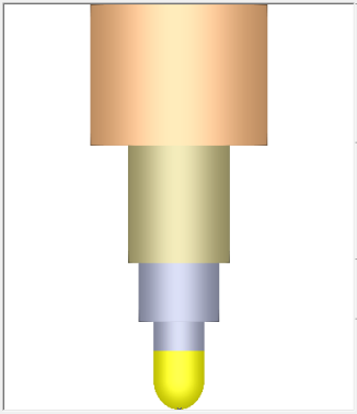
Display of Cutter 2 used in the procedure |
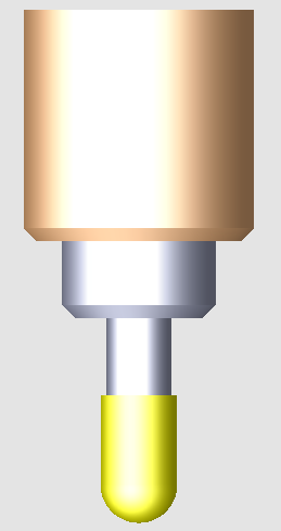
Display of Multi Cutters (Cutter 1+ Cutter 2) used in the procedure |

Cutter Tilting
|
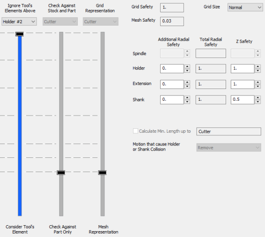
The following dialog status is displayed: The left slider is active and the middle and right sliders are locked to the bottom (Cutter). The Calculate Minimum Length up to parameter is grayed out and its checkbox is turned OFF The Motion that cause Holder or Shank Collision parameter is grayed out and locked to Remove. |
Example of cutter tilting sliders and parameters
|
Special Cases Involving Shank Diameter
If any part of the Shank has a diameter that is smaller than the Cutter's diameter, it will be considered as Shaft and will use zero safety.
|