Measurement Cycle: In-Process Measurement

Access: Open this function from one of the following locations:
-
Select the value field in the Measurement Cycle parameter of the Motion Parameters table branch.
Select the required cycle from the Cycle Selection dialog (to select a cycle, either double-click it or single click and then click Confirm and Continue).
-
Select the value field in the Cycle Data parameter of the Geometry Parameters table branch. The dialog for the cycle that appears in the Measurement Cycle parameter (above) is automatically displayed.
Optimize milling processes combined with feedback from part measurements while the part is on the CNC machine. This procedure performs part measuring operations on the CNC machine and validates the current machining results. You can chose whether to fine-tune successive machining operations (for example, change the cutter diameter compensation value) or to stop the machine to avoid out of tolerance machining.
The Cycle Selection dialog is displayed. All the available measurement cycles are shown in a tile-like display. Some machines support more cycle types while others do not support all the ones this procedure offers. Included are the cycle types that are the most commonly used. InvokeInvoke the required measurement cycle to display the relevant cycle dialog.
|
|
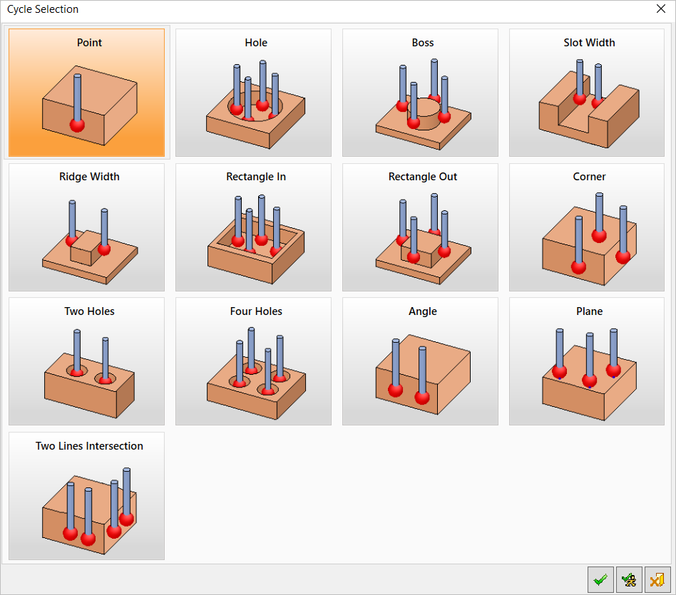
To select a cycle, either double-click it or single click and then click ![]() Confirm and Continue.
Confirm and Continue.
Dialog buttons
|
|
OK: Accept the changes, perform the operation, and close the current dialog/task. |
|
|
Confirm and Continue: Confirm the selection and continue to perform the operation. |
|
|
Cancel: Cancel all changes and close the dialog/task without saving the settings. |
Cycle selection process
When a cycle is selected, the following occurs:
-
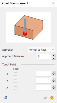
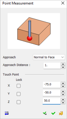
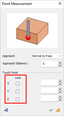
The relevant cycle dialog is displayed. Each measurement cycle has its own dialog with an image and relevant parameters, as shown below with the Point Measurement dialog.
-
Screen parameters are displayed to specify the lock options that display a plane on the selected lock axis and limits selection to that plane only. See Lock Options below.
-
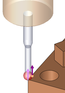
A measurement probe is displayed according to the selected cycle when geometry is selected or parameter data is entered manually. The parameters of the probe tool are defined in the Cutters & Holders dialog similar to any other tool in Cimatron.
|
Cycle Selection > |
Lock option parameters |
|||||||
|
|
See the Lock Options below. |
|||||||
|
Cycle dialog The numeric parameters, unless specified differently, are empty when entering the dialog. They can be set by clicking on geometry or by entering manually. The exact behavior depends on the specific cycle.
|
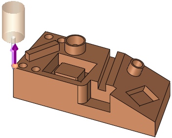
A probe is displayed according to the selected cycle when geometry is selected or parameter data is entered manually. The examples below show geometry selection.
|
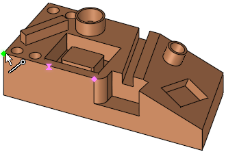
A point is selected |
The cycle dialog coordinates are updated |
|
|
|
|
The probe is displayed. A PINK arrow is shown on the picked point, showing the opposite direction to the probe approach motion (which is the direction the probe will advance towards the geometry while measuring). |
In this cycle, the approach direction is set normal to the picked face, but it can be changed to be along the X, Y, Z main direction or to a user-defined direction using the direction arrow. |
|
|
|
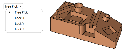
Lock options
Screen parameters are displayed to specify the lock options that display a plane on the selected lock axis and limits selection to that plane only. When a lock option is selected (not Free), an adjacent parameter value enables you to move the plane to the required position; selection will only be available on that plane.
|
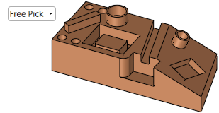
Free Pick enables selection with no plane limits |
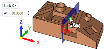
Selection is only available on the Lock X plane |
|
|
|
|
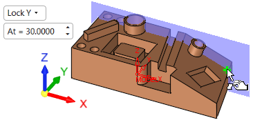
Selection is only available on the Lock Y plane |
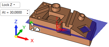
Selection is only available on the Lock Z plane |
|
|
|
Dialog Lock options
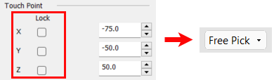
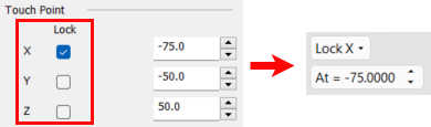
Lock options can also be selected from the various measurement cycle dialogs (the Point Measurement dialog below is used as an example).
When the Lock checkbox is ON (selected), the following occurs:
-
The screen parameters in the Graphic Pane automatically display the appropriate Lock option along with its corresponding value (see images below).
-
A BLUE plane appears. The At = screen parameter enables you to move the plane to the required position; selection will only be available on that plane.
-
If the value of the coordinate is changed, the screen parameter and blue plane will change accordingly.
When the Lock checkbox is OFF (unselected), the following occurs:
-
The screen parameter defaults to the Free Pick option and the coordinate values do not change.