Project  : Options and Results


Access: Open this function from one of the following locations:
-
Select Wireframe > Main Tools > Project from the menu bar.
-
Select Project on the popup menu if one or more curves, points, or edges are selected.
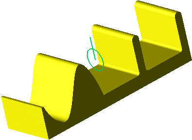
Project curves, edges, and/or points onto faces or planes.
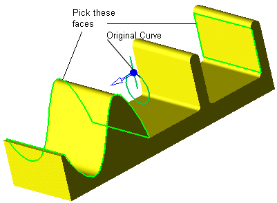
Required Step 1 
-
Pick the curve(s) to be projected.
-
Click <Exit><Exit> to proceed to the next step.
Required Step 2 
-
Pick one or more reference faces or planes and set the following parameters.

Parameters
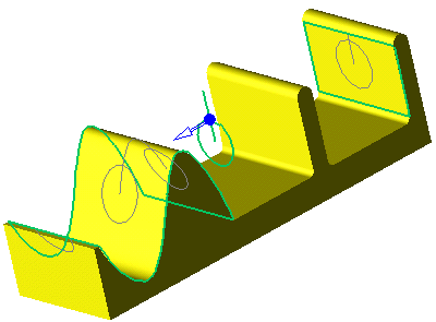
Direction Projection /
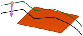
Normal ProjectionToggle option to set the direction of the projection. For 2D curves, the default direction is normal to the curve plane but you can use the arrow to set another direction.
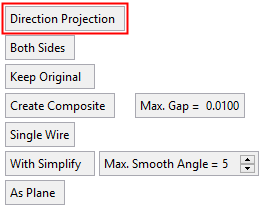
Direction Projection
Direction arrows are displayed enabling you to define the direction by which the curve is projected onto the face/plane. When this option is selected, the following toggle option is displayed:
One Side / Both Sides
Display projections on one or both sides of the curve selected in Required Step 1.
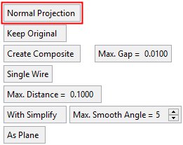
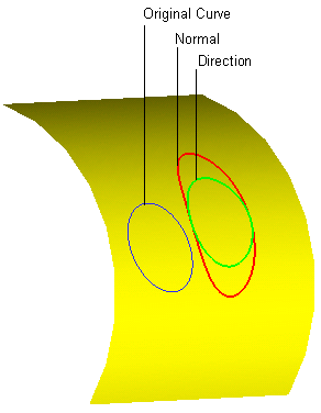
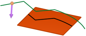
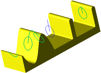
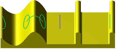
Normal Projection
The curve is projected normal onto the face/plane, as shown below. When this option is selected, the Max. Distance parameter is displayed (see below).
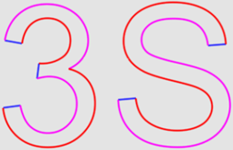
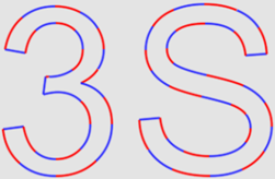
This is an example of both a Direction Projection and Normal Projection for comparison.
Keep Original / Remove Original
Toggle option to display or hide the original curve.
Create Composite / Don't Create Composite
Toggle this parameter to define the type of curve created by the function (see below for an example). When the Create Composite option is selected, the Max. Gap parameter is displayed.
Max. Gap
Enter the maximum gap tolerance allowed when creating the curve.
Examples of Composite CurveExamples of Composite Curve
When projecting a composite curve or a sketch (containing more than a single edge), the toggle option, Create Composite/Don't Create Composite, enables the result to either be a single composite curve or separate curves.
Create Composite
Don't Create Composite
Single Wire /
Multi WiresThis toggle option enables the creation of single or multiple wire bodies.
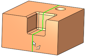
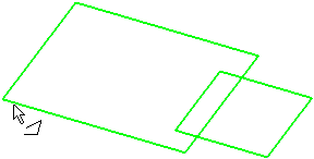
Single Wire
When numerous entities are selected, they are defined as a single wire (the group of entities is regarded as one entity). This is illustrated below where pointing to one of the wires (note the cursor symbol) highlights all the entities in the single wire.
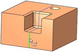
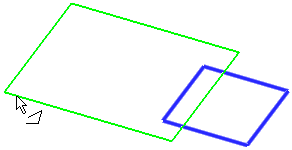
Multi Wires
When numerous entities are selected, they are defined as a multiple wires (the group of entities is regarded as multiple entities). This is illustrated below where pointing to one of the wires (note the cursor symbol) highlights only the relevant entity.
This option is displayed if Create Composite is selected above.
Max. Distance
Enter the Max. Distance for the projection. This option is displayed if Normal Projection is selected.
If you select a single reference face/plane, to achieve the desired result the Max. Distance value must be larger than the maximum distance between the curve (to be projected) and the reference face.
If you select multiple reference faces/planes, to achieve the desired result the Max. Distance value must be less than the distance to the nearest adjacent face.
ExamplesExamplesIn the example below, the BLACK curves are to be projected to their nearest reference faces. In this case, since each curve is very close to its nearest reference face, a small Max. Distance value is sufficient.
If a large Max. Distance value is defined, this may have an affect on adjacent faces. In this case, since the smallest reference face is 5mm, a Max. Distance value of the same amount causes one projected curve to affect an adjacent surface.
Similarly, if the Max. Distance value is increased over a certain threshold, all the projected curves affect adjacent faces.
With Simplify /
With SimplifyThis is a toggle option With Simplify /Without Simplify to simplify the resulting contours to allow for a higher quality result with less edges.
With Simplify
Simplify the resulting contours to allow for a higher quality result with less edges. This option simplifies the creation of contours by merging edges and is particularly useful when the geometry is composed of many small segments.
Example:Example:With Simplify:
When this option is selected, the additional parameter Max. Smooth Angle is displayed; this defines the maximum angle enabling you to control the smoothness of the contour.
Default = 5°
Min. = 0°, Max. = 45°.Without Simplify
Do not simplify the result to reduce the number of edges.
This is the default option.
Example:Example:Without Simplify:
This option is displayed if Create Composite is selected above.
As Plane /
As FaceOnce the direction has been set, pick the reference face(s) or plane(s) onto which the entities will be projected. More than one reference face or plane can be picked.
If the picked face is planar, an additional toggle option is displayed: As Plane / As Face. This option enables you to define the reference entity as either a plane or face, which in turn may affect the size/shape of the projection.
As Plane
Define the reference entity as a plane. The projection is previewed onto the plane.
ExampleExampleIn this case, the entire curve is projected onto the plane.
As Face
Define the reference entity as a face. The projection is previewed onto the face.
ExampleExampleIn this case, only part of the curve is projected (the part that "fits" onto the face):
Before accepting the results, a preview of the projection will be displayed in gray.
-
Click <Exit><Exit> to proceed to the next step.
-
Click OKOK
 or ApplyApply
 in the Feature Guide to complete the function. If you want to apply a draft angle to the projection (and you are projecting 2D curves), proceed to Optional Step 1.
Looking at the part in top view will better show the projection results.
Optional Step 1 
- Define a draft angle for the projection
- Click OKOK or ApplyApply in the Feature Guide to complete the function.
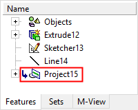
When completed, the Project feature will appear in the Feature Tree.