Machine Definition  : Multi-Spindle Support
![]()
![]()
Access: Open this function from one of the following locations:
-
Select NC Utilities > Utilities > Machine Definition from the menu bar.
-
Cimatron Control Panel: Select Start > All Programs > Cimatron > Cimatron Control Panel.
Select NC > Machine Definition.
This application enables you to construct a machine definition for the Machine Simulator. It enables defining the kinematics tree structure, the axes, and the displayed components of the CNC machine. This enables you to simulate the G-Code motions on a virtual machine that imitates the real machine behavior.
Important! This application is for use by qualified personnel only. Contact your Cimatron Provider or Reseller to get a machine definition for the Machine Simulator.
The simulation of additional spindles in the Machine Simulator is handled as follows:
-
The simulator needs to be told on which spindle to mount the cutter. This is done in the post processor by using the SIM_SPINDLE_NUM variable.
-
Any shift, in case there is some distance between the main and secondary spindle face point, should be taken care of by the post processor. This is done by using the X_SIM_OFFSET, Y_SIM_OFFSET, Z_SIM_OFFSET variables.
Multiple spindle support covers the following cases:
-
Replacing the existing spindle component. In the example shown below, a machine has three different heads which need to be replaced:
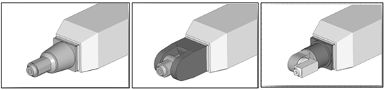
-
A secondary spindle is an add-on to the main one. In the example shown below, a knee-head is mounted on the main spindle:
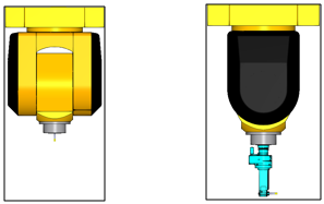
When considering multi-spindle support for the Machine Simulator, the machine should be built in such a way that inactive spindle components are automatically hidden and ignored for collision checking.
Multi-spindle machine definition
A knee-head case is used as an example for the machine definition.
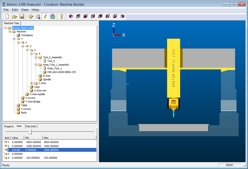
In this case, the focus is on the main spindle, which is attached to the tilting axis A, and the secondary spindle which is in the knee-head.
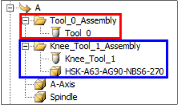
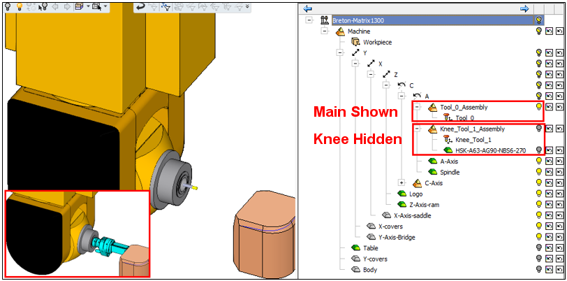
Note that the A-Axis and Spindle components are mounted on rotary axis A. There are also two sub-assemblies, highlighted above.
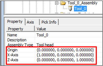
- In the first sub-assembly there is the TOOL_0 component.
- The properties show that this is a vertical tool (the main spindle tool is a vertical tool).
- The "_0" in the name also identifies this as the main tool component.
- Information sent from the GPP2 Post Processor to the simulator about SIM_SPINDLE_NUM = 0 refers to the cutter mounted on this spindle - "_0".
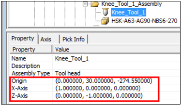
- The second sub-assembly contains the Knee_Tool_1 component.
- The properties show that the tool is aligned with the Y axis (90° to the main tool).
- The shift distance between the main and the knee-head spindles is set in the Origin row as shown below.
- Information sent from the GPP2 Post Processor to the simulator about SIM_SPINDLE_NUM = 1 refers to the cutter mounted on this spindle - "_1".
Naming Convention
The following naming convention should be followed.
- The main tool assembly component is always "_0" (or none).
- Any additional tool components should be named "_1", "_2".... "_n". Any string can be added before or after these particular strings.
- The second sub-assembly also contains the knee-head component itself.
These sub-assemblies separate the active and non-active parts during simulation. To make this possible, the sub-assembly names should match the string ("_1", "_2".... "_n") used by their contained tool components.
Any string can be added before or after these particular strings. The additional strings can be different from those of the tool component; for example Knee_Tool_1 and Knee_Tool_1_Assembly. The importance here are the "_1" characters. When the simulator gets a command that tool *_0* is active, it will display the *_0* sub-assembly components and only consider them for collision checking. The inactive components (knee sub-assembly *_1*) are hidden and will not be checked for collision.
The image below shows the functionality in the simulator. The cutter is mounted on the main spindle. The knee, although existing, is hidden by default (it can be displayed manually)—It is not considered for collision checking, even when shown.
Summary
-
The main tool assembly component is always "_0". Note that if there is only one spindle, this naming rule is irrelevant.
-
Additional tool assembly components should be named "_1", "_2".... "_n". Any prefix and postfix is allowed.
-
Different orientation tools must be set in the additional tool properties dialog.
-
The shift distance between main and additional tools must be set in the additional tool properties dialog.
-
Sub-assemblies are needed for visibility and collision check consideration.
-
Sub-assembly names should contain the same guarded tool assembly names - "_1", "_2".... "_n". Any prefix and postfix is allowed.