|
|
Clean Between Passes and Ridges
While the tool is moving along the procedure’s main lanes, it may leave unmachined areas.
Intermediate motions, known as Clean Between Passes, may be added to machine these areas and also to reduce scallops.
The Clean Between Passes branch enables you to define the level of control over its use and over the display of the parameters in the branch. The following branch options are available: No, Basic, and Advanced.
-
Show the motions of the procedure in the second toolpath (named CBP).
The displayed motions are the result of a Finish Mill All procedure with Round Corners calculated in Basic mode and no Clean Between Passes activated.
-
Duplicate the procedure and edit it.
In the Clean Between Passes branch, select the Basic option. -
Execute the procedure.
-
Toggle the motion display to view the difference between the two procedures. Notice the additional motions in the Clean Between Passes and Ridges procedures.
-
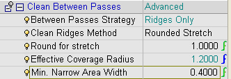
Duplicate the procedure and edit. Select the Advanced option.
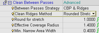
Note that the Advanced mode displays more controlled parameters.
The first parameter deals with the Between Passes Strategy and includes 3 options:-
CBP and Ridges – Combination of the two motion types.
-
Ridges OnlyRidges Only – Creation of only ridge motions.
-
CBP OnlyCBP Only – Creation of only Clean between Pass motions.
-
-
Select Ridges Only.
Set the parameters as shown in the following image:
-
Save & calculate the procedure.
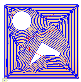
Note the differences between the procedures. Note that the Ridges Only option covers only the ridges and not the Between Layers unmachined areasBetween Layers unmachined areas.
The Effective Coverage Radius allows you to control the detection of the unmachined areas. This parameter indicates how big the unmachined area is and whether it needs to be machined by extra clean motions. Value range is between <0.6 * Side Step> and <0.99 * Side Step> or <0.99 * Tool Diameter/2>.
In the example below, the effective tool that the user has defined is small and, therefore, the unmachined area between the lanes is large. In this case, an extra motionextra motion will be performed to cover this unmachined area.
A small effective coverage radius maximizes the number of areas that will be detected as unmachined areas.
A large effective coverage radius minimizes the number of areas that will be detected as unmachined areas.
In the image below, the PURPLE procedure was created with a small effective coverage radius.
Min. Narrow Area Width controls the minimum area size to be considered. Motions will not be created for an area size that is less than this value. This value is useful for preventing the creation of a scattered toolpath that results from long areas that are very close to the definition of CBP.
The value range is between <0> and <0.99 * (Tool Diameter – 2 * Effective Coverage Radius)>.
- Set the Effective Coverage Radius to its minimum value to ensure that the scallop height is minimal. A small Effective Coverage Radius should usually be used for finish operations and a large Effective Coverage Radius value should be used for Rough operations.
- To make sure the Effective Coverage is always at its maximum value in all combinations of side step and tool, it is recommended to define it as a formula: 0.5 * Tool Diameter.
- Although a larger Minimum Narrow Area Width value results in higher scallops, it usually improves the surface quality by reducing the number of tiny motions.
![]()
![]()
![]()