|
|
Bend  : Options and Results
Access: Open this function from the following location:
Access: Open this function from one of the following locations:
-
Select Solid > Warp > Bend from the menu bar.
-
Select Die Design > Geometry Manipulation > Bend from the menu bar.
-
Select Bend from the following Die Design Guide: Die Process Design Guide (Forming).
Bend objects around an axis.
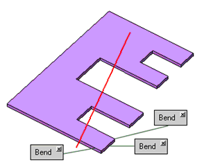
This function can be used to bend objects relative to the selected neutral plane and bending line.
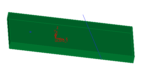
To demonstrate the results of the Bend function, the following part is used:
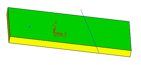
Required Step 1 
Pick the object or objects that you want to bend relative to the selected neutral plane and bending line.
An open object may also be picked. If only one object exists, it will be automatically picked.
Press <exit><exit> when all objects are selected.
Required Step 2 
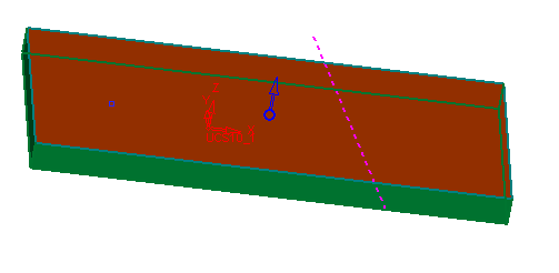
Define the neutral plane and the bending line and press <exit><exit>.
Required Step 3 
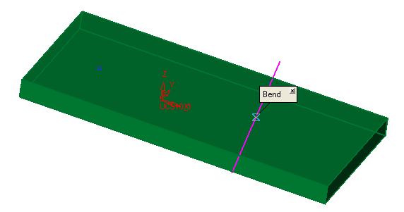
Define the bending direction and parameters as required. The following parameters are displayed:

Set the parameters as required:
|
Thickness |
Enter the thickness of the object. The default value is derived from the Die Setup dialog in the DieDesign application. If this value has not been defined in the Die Setup dialog, the thickness is calculated. If it cannot be calculated, the default value is 2 mm (0.1 inch). |
||
|
K - Factor |
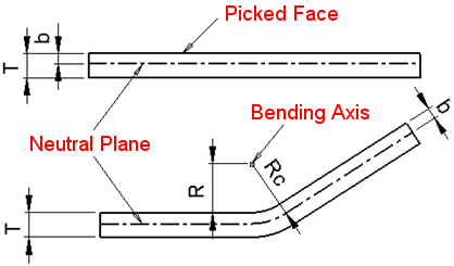
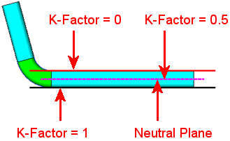
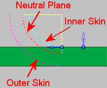
Enter the required K Factor. During bending, the inner skin of the bend is subjected to compression while the outer skin is subjected to tension. However there is a layer in-between which is free from any forces and thus its length remains the same. This is called the neutral plane. The K-Factor (K) is the ratio that represents the location of the neutral bending plane (b) with respect to the thickness of the object (K = b / T).
The default value is derived from the Die Setup dialog in the DieDesign application. If this value has not been defined in the Die Setup dialog, the default value is 0.5.
|
||
|
Angle |
Set the angle of the bend operation. |
||
|
Radius - Neutral Plane |
This is a dropdown list which enables you to define how the Bend Radius is applied. The following options are available:
See the description for K - Factor above, for an explanation of these terms. Notes:
|
||
|
Bend Radius |
Set the bend radius value to be applied to the plane/skin defined in the previous parameter. |
Optional Step 1 
Pick the reference point for a local bend.
Click OK ![]() or Apply
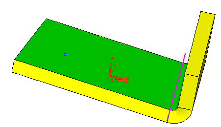
or Apply ![]() in the Feature Guide to complete the function. The object is bent along the selected bending line in the selected upper direction, as follows:
in the Feature Guide to complete the function. The object is bent along the selected bending line in the selected upper direction, as follows:
Additional Examples
|
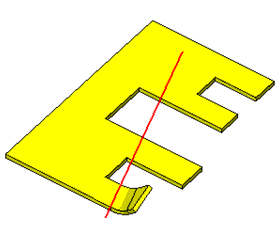
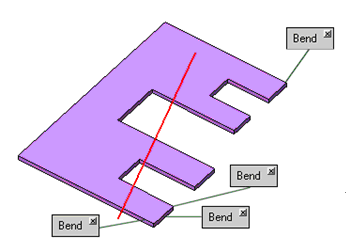
In this example, the user picked many points in a single area to bend, as shown below. You can pick one or many points in the same area and the result will always be the same, as shown on the picture on the right. |
||
|
|
|
|
|
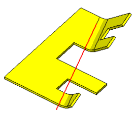
In this example, the user selected an additional point in a different area. The result is displayed accordingly, as shown in the picture on the right. |
||
|
|
|
|
When completed, the Bend feature will appear in the Feature Tree as follows:

data-condition="Others:PRINT_version_NO" href="/Deleting_a_Feature.htm" style="text-decoration: none; ">
|


