|
|
Cylinder Centerlines 


Access: Open this function from the following location:
-
Select Wireframe > Derived Curves > Cylinder Centerlines from the menu bar.
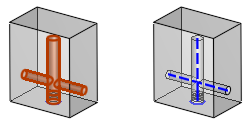
Create a path of cooling circuit centerlines along one or more cylinder or cone faces (holes or shafts) in a part.
This feature is available in the Part and Assembly environments and does not require a Cimatron Mold license. It is well suited for users that do not cut cooling holes.
General Interaction
-
Select Cylinder Centerlines from the menu bar.
(Click Access above for information on how to access this feature.) -
The Cylinder Centerlines Feature Guide appears. The Feature Guide displays two Required Steps that are used to select and define the path for the Cylinder Centerlines.
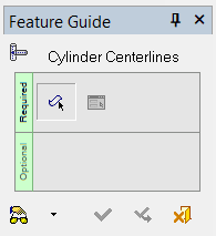
 Tip: You can open the Feature Guide at any time by right-clicking the mouse in the graphic display area.
 -
Required Step 1
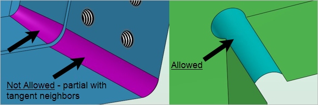
 : Pick a cylinder or cone face. The cylinder will be automatically selected as well as any connecting cylinders. When you have selected all faces, exit to proceed to Required Step 2.
Note: Partial cylinders/cones that have a tangent neighboring face along the straight edge cannot be selected. Only full cylinders/cones with faces that revolve 360 degrees and share a straight edge can be selected using this feature.
-
Required Step 2
 : Define the feature's parameters.
Parameters
|
Trim On / |
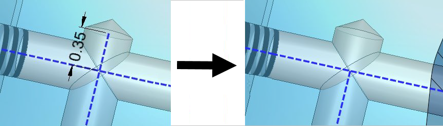
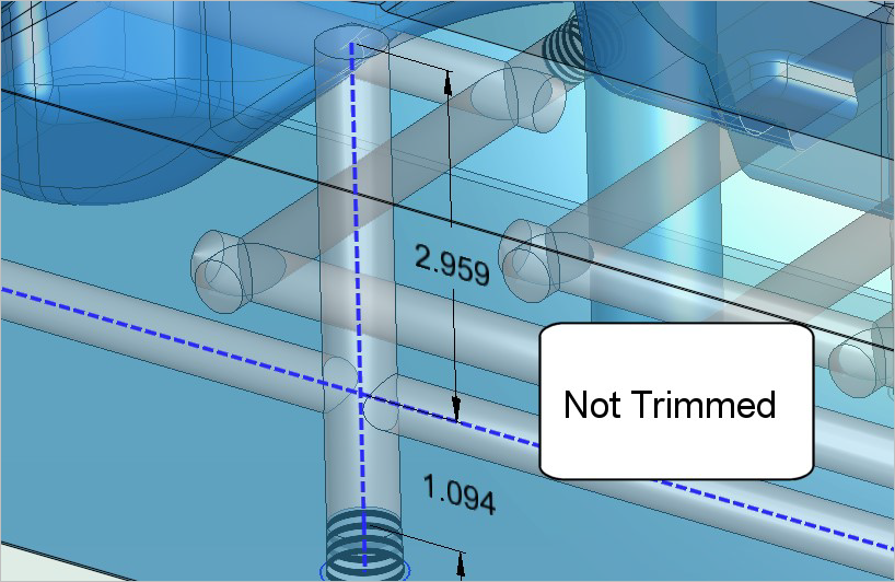
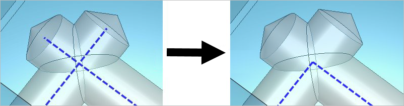
When the Trim On toggle option is selected, Cimatron measures the length of every line segment and removes those lines that meet the following criteria:
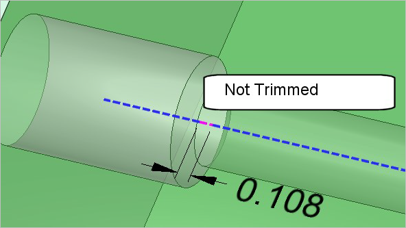
The image below shows a line segment that was not trimmed because its length is greater than the value set for the Max. Distance for Trim parameter
When Trim Off is selected, no trimming occurs. The default setting for this screen parameter is Trim On. |
|
This screen parameter is only displayed when the Trim On option is selected.
|
|
|
Create Sets / |
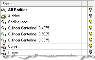
When the Create Sets toggle option is selected, the centerlines are organized into Sets based on their respective cylinder diameter. Only the lines that belong to each set are merged to create the centerlines. The Sets are listed in the Feature Tree with the following naming convention:
When Don't Create Sets is selected, Sets are not created. Note that pre-existing Sets will not be removed when this option is selected. The default setting for this screen parameter is Create Sets. |
|
Single Color / |
When the Single Color toggle option is selected, all geometry is created using the active curve color, width, and style. When Sequential Color is selected, all geometry is created using the active width and style. The lines that share the largest found cylinder diameter are created with the active color. All lines with the second largest cylinder diameter are created using the next color in the standard color palette, and so on. The default setting for this screen parameter is Sequential Color. |
-
Click OKOK
 or ApplyApply
 in the Feature Guide to complete the function.
Detailed Interaction
See Options and Results.
|