|
|
Component Drilling  : Options and Results
Access: Open this function from one of the following locations:
Define the required drilling machining depth and time by calculating the total required drilling depth on defined holes, based on Diameter groups.
The holes can be defined automatically, or manually added; the Hole Table displays the relevant data. This information is used later when generating quoting data.
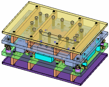
The following assembly is used to describe this function:

When you openopen this function, the Component Table is displayed. The table displayed here is not the full Component Table (as defined in the Components function), but a table only showing data relevant to the current operation.

Required Step 1 
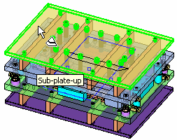
- Select the component on which the total required drilling depth is to be calculated. Only predefined components can be selected.
The component can either be picked in the display area or selected from the Component Table.

- When selected, the component is displayed in transparent mode and the other components are hidden, for clarity.
The function automatically moves to the next step.
Required Step 2 
-
Add predefined drills or create a new drill set. When you enter this step of the function, the Component Table is closed, the Hole Table is opened (containing data for the selected component - see below) and the following parameters are displayed:

Add All Holes
Add all the predefined holes to the Hole Table (see below). These holes are automatically recognized and grouped according to their geometry, size and other attributes.
Grouping rules consist of diameter ranges (see the Edit Drill Ranges parameter below) and the complexity of the holes (see the Complex Hole parameter below).
New Hole
Manually define a new hole by adding it to the Hole Table (see below). To select a hole and add it to the Hole Table, pick a face or a point. Multiple holes can be selected.
When you select this option, the following parameters are displayed:
Diameter
Set the diameter of the new hole(s).
Notes:
-
If a single cylinder face is selected, the system automatically calculates the Diameter; otherwise you need to manually enter the diameter.
-
If the values are valid (positive numbers), the Hole Table is updated with the new Hole, according to the diameter (type definition).
-
If the values are invalid or missing, an appropriate message is displayed prompting you to either change or enter values.
Depth
Set the depth of the new hole(s).
Simple
This is a toggle option Simple / Complex that defines the complexity level of hole.
Ignore Assigned
This is a toggle option Ignore Assigned / Select All that informs the system to either ignore holes that have already been assigned or to select all the holes and assign them in the Hole Table.
Edit Drill Ranges
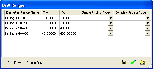
Define the drill diameter ranges. The Drill Ranges dialog is displayed:

A row of data in the table always takes values from the previous row (if available).
Diameter Range Name
Define the range name. The default naming system is Drilling ø x-y, where x and y are the From and To values respectively.
From / To
Set the range values. Only the To parameter can be edited; the next row's From parameter is automatically updated accordingly to the previous row's To parameter.
Simple / Complex Pricing Type
Define the pricing type by selecting a value from the appropriate dropdown list.
The following appear at the bottom of the table:
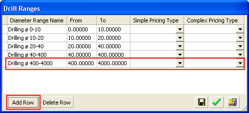
Add Row
Add a new row at the end of the list. The next row's From parameter is automatically updated accordingly to the previous row's To parameter.
Example:Example:
Delete Row
Delete a selected row (plate set). If a following row exists, the system automatically updates its From value.

Save the setup for all future quotes.

Change the setup, only for this file, and close the dialog.

Cancel the setup.
When the Drill Range data is changed and saved, the range names are copied to the Hole Table (see below) and all values (automatic and manual) are cleared from the Hole Table and the lines are adjusted accordingly.
Complex Hole
Set the following Complex Hole parameter options:

These consist of assigning a Thread attribute and Accurate Hole attributes to the hole.
The following Hole Table is displayed showing drill data (by diameter range) for the selected plate:

A row of data in the table always takes values from the previous row (if available).
Color
The color of the holes within a diameter range are defined automatically. Change the color by picking the color icon and selecting the color from the displayed color palette.
Drill Name
The drill name is defined automatically and consists of the name of the selected plate + an automatic numbering sequence (D1, D2, etc.).
Diameter Range Name
Taken from the Drill Ranges dialog (see the Edit Drill Ranges parameter above). This parameter cannot be edited in this table.
Simple Pricing Type
Taken from the Drill Ranges dialog (see the Edit Drill Ranges parameter above), however, the value can be changed from the dropdown list.
Total Simple Depth
Simple Machine Time
Set the required machining time factor. The last defined machine time is used for any new operation. By default this is set to 1.
Complex Pricing Type
Taken from the Drill Ranges dialog (see the Edit Drill Ranges parameter above), however, the value can be changed from the dropdown list.
Total Complex Depth
Complex Machine Time
Set the required machining time factor. The last defined machine time is used for any new operation. By default this is set to 1.
Num. of Segments
Comment
Enter a comment as required.
-
- Click OKOK or ApplyApply in the Feature Guide to complete the function.
|
