|
|
Symmetry Ordinate Dimensions

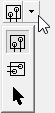
Access: Open this function from one of the following locations:
-
Click the
 button in the toolbar.
 -
Select Symbols > Textual > Dimension from the menu bar.
-
Select Dimension on the popup menu (right-click the graphics area).
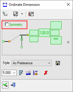
Create Symmetry Ordinate dimensions. A symmetry ordinate dimension is created when a symmetry or center line is involved in the dimensioning process (e.g. if a point on a symmetry or center line is selected during the dimensioning process). In this case, a Symmetry checkbox appears in the dimension dialog.
|
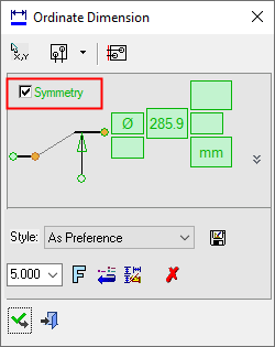
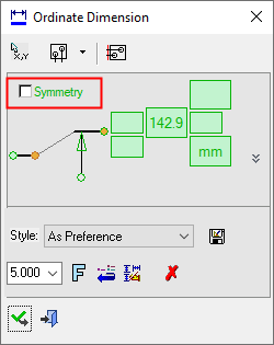
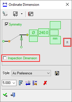
Symmetry Ordinate Dimension dialog: Click on an item in the dialog for a description. See below for additional information. |
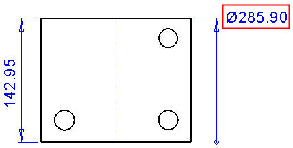
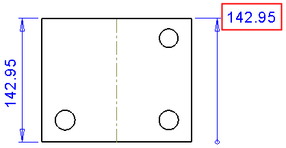
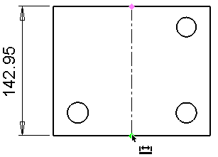
Example Symmetry Ordinate dimension: |
|
|
|
|
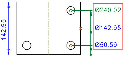
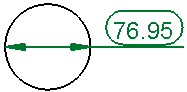
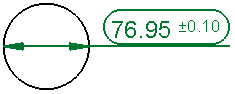
Symmetry = ON |
|
|
|
|
|
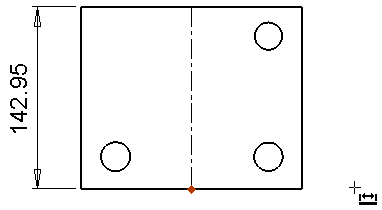
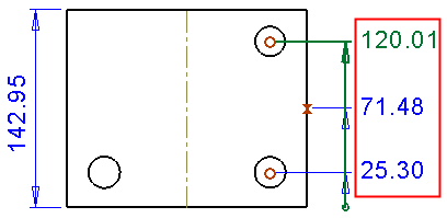
Symmetry = OFF |
|


- See the Symmetry Ordinate Chain dimensions below and also Ordinate dimensions.
- See the Advanced Area Options, later in this topic.
Creating a symmetry ordinate dimension
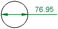
In the examples below, the dimension on the left displays the real dimension size; the symmetry ordinate dimension will be created on the right.
Create an Ordinate dimension where the base of the ordinate dimension is on a symmetry or center line; the result will be a symmetry ordinate dimension.
Pick an origin point; in this example on a symmetry line.
Pick a point in the graphic area through which the ordinate line will pass.
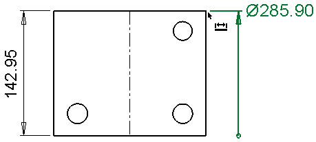
Pick the target point, center line or symmetry line. The symmetry ordinate dimension is displayed. When the Symmetry checkbox is ON, a diameter symbol is displayed with the dimension.
Edit its parameters with the help of the hot spots and tips either directly in the graphic area or on the popup submenu. Change the font style ![]() and character size also, if required.
and character size also, if required.
Press <exit><exit> when finished.
Note: For additional information, see the Dimensioning Process and the attached notes.
Ordinate Dimensions Positioning Options
Set general ordinate dimension definitions. This section works in stages from left to right.
|
|
Stage 1: Pick the dimension Base Point Command button. This button is selected by default and can be reselected to pick a different base point. Pick the next dimension point to indicate the dimension direction. |
|||||
|
|
|
|
|
|
|
|
|
Stage 2: |
|
Stage 3: |
||||
|
|
|
Ordinate Direction: Horizontal: Display the ordinate chain horizontally. |
|
 |
Select Ordinate Distance: The first dimension is created at the distance from the selected point defined in the Preferences. Click this button, to select any point and all aligned dimensions will move to it. Once a selection is made, this mode is exited automatically, however, you can also exit this mode using the MMBMMB or the ESC key. |
|
|
|
Ordinate Direction: Vertical: Display the ordinate chain vertically. |
|
||||
|
|
Ordinate Direction: By Selection Define the direction to display the dimension line by picking two points or a line. |
|
||||


Once these stages are complete, you can start selecting the points for the ordinate dimensioning.
Symmetry Ordinate Chain
When the Symmetry checkbox is OFF, the real dimension size is shown; this is the default state. When the Symmetry checkbox is ON, the dimension is a symmetry ordinate dimension and is shown as double the real dimension size (in addition, a diameter symbol is displayed with the dimension). This is also the case for symmetry ordinate chain dimensions; turning the checkbox ON and OFF affects the checkboxes of the entire chain.
Note: The method for creating Symmetry Ordinate Chain dimensions is the same as that for Ordinate Chain dimensions (press <exit><exit> between the dimensions of the chain).
| Symmetry checkbox ON: the chain displays the symmetry ordinate dimensions (double the real dimension sizes) and also the diameter symbol. | |
|
|
|
| Symmetry checkbox OFF: the chain displays the real dimension sizes. | |
|
|
|

Advanced Area Options
All Dimension dialogs have an Advanced Area where additional dimension options are available. Click the Expand toggle button ![]() on the Dimension dialog to show the Advanced Area parameter(s).
on the Dimension dialog to show the Advanced Area parameter(s).
The Inspection Dimension option appears in all the Dimension dialogs; however, additional options may also appear here depending on the entity selected to be dimensioned.
|
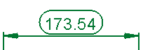
Inspection Dimension |
Surround dimensions with a rounded outline. This means that it is a dimension that should be inspected/verified after production.
|
|