Symmetry Line

Access: Open this function from one of the following locations:
-
Click the
button in the toolbar. -
Select Symbols > Symbols > Symmetry Line from the menu bar.
-
Select Drafting Symbols > Symmetry Line on the popup menu (right-click the graphics area).
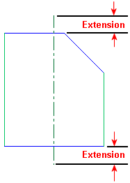
Add a symmetry line to a drawing. In addition, you can define the amount by which the symmetry line extends both sides beyond the defined area.
|
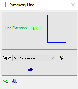
The Symmetry Line dialog displays
|
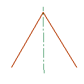
Below is an example of the symbol:
See Entity Overview for a general description. |
||||
Create a Symmetry Line
-
InvokeInvoke the Symmetry Line function.
-
The function dialog is displayed. Pick either two points, two lines (parallel/ intersectingintersecting
 ) or a line and a point.
 -
Edit the Line Extension parameter either in the dialog or by clicking the symmetry line.
-
To complete the current operation and remain in the dialog, press the Apply
 button or <exit><exit>.
To exit the function, press the Close button.
Notes:
-
Right-click the entity itself to access the entity-specific (for editing) and general functions from the popup submenu.
-
Double-click the entity to edit it.
-
The symmetry lines can be selected for regular dimensioning operations, however, it is important to note that the position on the symmetry line that you pick, could influence the resulting dimension.
-
The parameter values you select are saved. The next time you access this tool, the last selection is displayed as the default. See Keep Last Parameter Value.
-
See the Symbol notes for additional information.