|
|
Dimension Process 

Access: Open this function from one of the following locations:
-
Click
in the toolbar. -
Select Symbols > Textual > Dimension from the menu bar.
-
Select Dimension on the popup menu (right-click the graphics pane area).
Any view entity can be dimensioned. The Dimension dialog that is displayed and the subsequent dimension type displayed on the view are dependent on the type of view entity selected to be dimensioned. For example, if a line is selected, the Linear Dimension dialog is displayed and a linear dimension type is displayed on the view.
The general procedure for dimensioning an entity is as follows (also see the notes below):
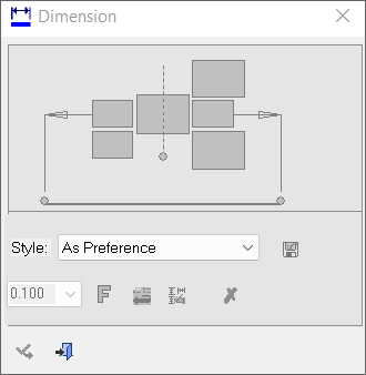
InvokeInvoke the Dimension function. A grayed out Dimension dialog is initially displayed.
Pick the entities to be dimensioned and re-position the drafting entity by picking a point on the screen. This will define the new position of the dimension label (The label will move to the picked point).
The Dimension dialog now displays the relevant labels and values; the example below is for a radial dimension.

Edit the dimension using one of the following methods:
-
Directly in the graphic area by moving the cursor around the dimension to various hotspots where dimension parameter tips appear. These can be modified by clicking on them and entering their values.
-
Modifying the dimension parameters in the popup submenu by clicking on them and entering their values. The dimension is automatically updated.
Exit by clicking the middle mouse button.
Notes: General
-
Right-click on the entity itself to access the entity-specific (for editing) and for the general functions from the popup submenu.
-
Double-click the entity to edit it.
-
Some of the parameter values you select are saved. The next time you access this tool, the last selection is displayed as the default (see Keep Last Parameter Value).
-
Creating a PMI dimension (in the Modeling environment) is very similar to creating a dimension in the Drafting environment, even though modeling is a 3D environment and drawing is a 2D environment.
-
See the Symbol notes for additional information.
Notes: Dimension Type-Specific
-
For Linear Dimensions:
-
See Align to Symbol to align the new dimension with an existing one.
-
A Ø symbol is added as a dimension prefix when the system can determine that the underlying feature is a round hole, shaft, or cylinder.
-
-
For Linear and Radial Dimensions:
-
Dimensions created on edges of faces with a hole attribute or thread/tap attribute will get the data automatically; this is applicable to linear or radial dimensions.
-
If a hole attribute (of the type Accurate Hole) or a thread/tap attribute is attached to the face being dimensioned, a checkbox is displayed in the Dimension dialog enabling automatic update of the dimension.
-
See Dimension Dialog for Radial Dimensions and specifically the Automatic Accuracy and Automatic Thread/Tap explanations in Radial Dimensions.
-
-
For Radial Dimensions; A jogged (broken) radial dimension can be defined when the center of a large arc is located far off and cannot be displayed in its true location. See Dimension Dialog for Radial Dimensions and specifically the Jogged Dimension.
-
For Hole Dimension labels; Use the Hole Dimension function to create a dimension label with the full data (size and tolerance) of the hole which complies with the ANSI, JIS, or ISO standard.
|