EDM Setup  : Electrode Parameters

Access: Open this function from one of the following locations:
-
Select Electrode > Tools > EDM Setup from the menu bar.
-
Select EDM Setup from the Electrode Guide Toolbar.
-
Right-click a Component
 , UCS
, UCS
 , Folder
 , Electrode
or Location
, Electrode
or Location
 in the Electrode
Tree to display the popup
menu and then select EDM
Setup.
in the Electrode
Tree to display the popup
menu and then select EDM
Setup.
The EDM Setup Electrode Parameters ![]() are displayed as follows (browse the EDM tree within the EDM Setup dialog to display the parameters relevant to the selected item).
are displayed as follows (browse the EDM tree within the EDM Setup dialog to display the parameters relevant to the selected item).
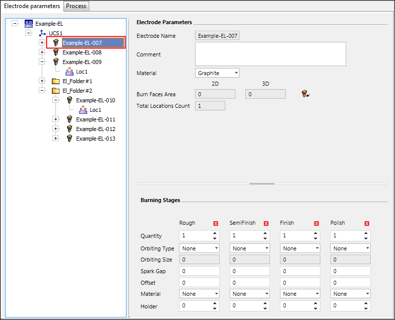
When selecting the Electrode, the following parameters are displayed.
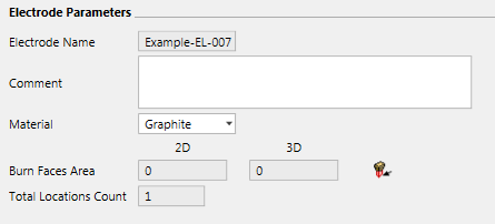
Electrode Parameters
The following parameters appear in the Electrode Parameters section:
|
Electrode Name |
The name of the electrode and its number as it appears in the Electrode Tree on the left. |
|||||||||
|
Comment |
Enter a comment if required. |
|||||||||
|
Material |
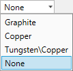
Select the electrode Material from the dropdown list.
|
|||||||||
|
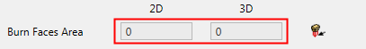
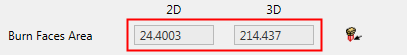
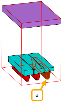
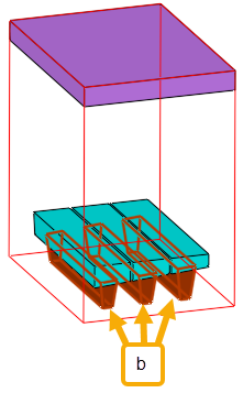
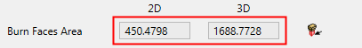
Burn Faces Area |
This area displays the 2D (projected) and 3D (total) burning face areas. This value is required by various EDM machines to optimize the burning process. Press the
Unselect the non-relevant faces and click OK Upon completion, the 2D and 3D burning face area fields are updated automatically.
The last selection of faces for each electrode is kept. As a default, the system will select all burning faces, however the system always keeps the last selection status for each electrode, so if you select/unselect faces, in Edit mode the last selection is available. To reset the selection (set to default) click the All Burning Faces screen parameter in the Area function.
The All Burning Faces button restores the system default of selecting all the burning faces of the electrode. This is useful if the electrode has multiple burning faces and you have manually unselected some of them. The calculation of the 2D and 3D burning face areas is based on the selected burning faces.
Clicking All Burning Faces will return higher surface area values.
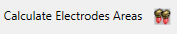
In the Component Parameters page of the dialog, the Calculate Electrodes Areas considers the last selected faces, so it works based on the last selection of each electrode. |
|||||||||
|
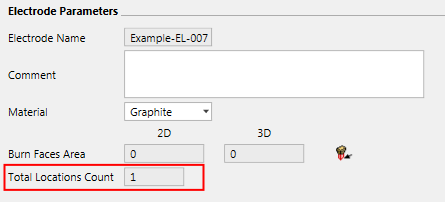
Total Locations Count / Locations Count |
The number of locations for this electrode. If an electrode only appears once (all its locations are under the same folder/root), the Total Locations Count field is displayed, as shown below:
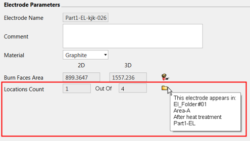
If an electrode appears more than once, the following data is displayed:
|
|||||||||
 button to calculate these areas. This operation invokes the
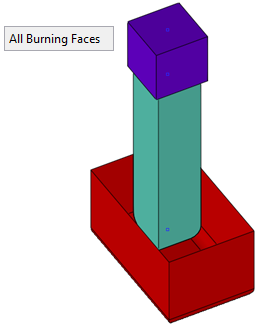
Burning Stages
The following parameters appear in the Burning Stages section:
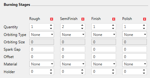
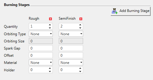
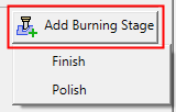
Each burning stage (Rough, SemiFinish, Finish or Polish) can be hidden by pressing on the X in the appropriate column header. At least one burning stage must appear. Once a burning stage is hidden, the Add Burning Stage button appears and clicking this button displays a dropdown list of the hidden burning stages; click a stage from this dropdown list to re-display it the dialog.
|
In the example below, the Finish and Polish burning stages are hidden. The Add Burning Stage button appears and, when clicked, displays a dropdown list of the hidden burning stages. Click a hidden stage to re-display it the dialog. |
|
|
|
|
For each of the burning stages (Rough, SemiFinish, Finish or Polish), the following parameters can be set:
|
Quantity |
The number of electrodes at each burning stage. |
|
Orbiting Type |
Select the Orbiting Type from the dropdown list.
|
|
Orbiting Size |
Set how much the electrode rotates. |
|
Spark Gap |
The distance between the electrode and the workpiece when discharges are occurring. |
|
Offset |
This parameter defines the difference between the actual electrode and the designed electrode. (The actual electrode is geometrically smaller than the designed electrode). In essence, this parameter defines how much material should be left after the burning, for the next electrode operation. This parameter is used by the CMM measuring function which, while inspecting an electrode, considers the burning parameters. |
|
Material |
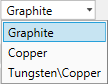
Select the specific electrode Material from the dropdown list.
|
|
Holder |
The number of holders at each burning stage. |