|
|
Electrode Tree Popup Operations
Electrode Tree popup submenus are displayed by right-clicking on an item in the appropriate tree. The popup submenu displayed will depend upon the level of the item selected.
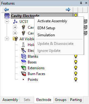
ComponentComponent ![]() : This level represents the main assembly and all the mold components which are not electrode files.
: This level represents the main assembly and all the mold components which are not electrode files.
Activate Assembly, EDM Setup, Simulation, Update & Disassociate, Ignore Update.
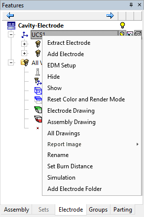
UCSUCS ![]() : This level represents reference UCSs that were used during the electrode extraction. Each UCS represents an orientation of the mold component on the EDM machine.
: This level represents reference UCSs that were used during the electrode extraction. Each UCS represents an orientation of the mold component on the EDM machine.
Extract Electrode, Add ElectrodeAdd Electrode, EDM Setup, HideHide(hide
all the locations ![]() under the UCS
under the UCS ![]() ), ShowShow(show
all the locations
), ShowShow(show
all the locations ![]() under the UCS
under the UCS ![]() ), Reset Color and Render Mode, Electrode Drawing, Assembly Drawing, All Drawings, Report Image, RenameRename, Set Burn Distance, Simulation, Add Electrode Folder.
), Reset Color and Render Mode, Electrode Drawing, Assembly Drawing, All Drawings, Report Image, RenameRename, Set Burn Distance, Simulation, Add Electrode Folder.
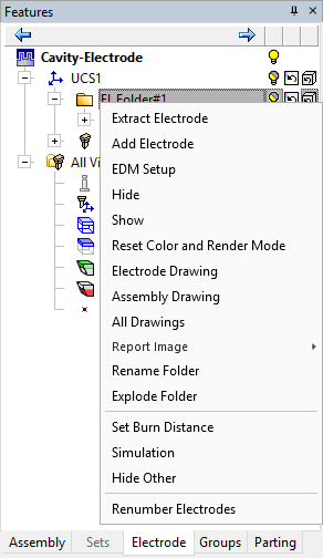
FolderFolder ![]() : Electrodes can be put into folders for sorting and control purposes.
: Electrodes can be put into folders for sorting and control purposes.
Extract ElectrodeExtract Electrode, Add ElectrodeAdd Electrode, EDM SetupEDM Setup, Hide/ShowHide/Show, Reset Color and Render Mode, Electrode DrawingElectrode Drawing, Assembly DrawingAssembly Drawing, All DrawingsAll Drawings, Report ImageReport Image, Rename FolderRename Folder, Explode FolderExplode Folderremove the contents of the folder and return them to their original location in the tree; the selected folder is deleted), Remove FolderRemove Folder, Set Burn DistanceSet Burn Distance, SimulationSimulation, Hide OtherHide Other, Renumber ElectrodesRenumber Electrodes.
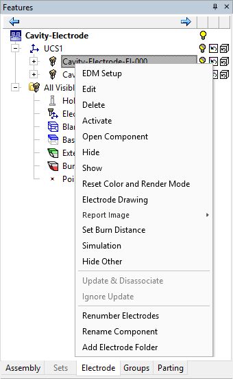
ElectrodeElectrode ![]() : This level represents electrodes which exist in the assembly.
: This level represents electrodes which exist in the assembly.
EDM Setup, EditEdit, DeleteDelete, ActivateActivate, Open Component, HideHide, ShowShow, Reset Color and Render Mode, Electrode Drawing, Report Image, Remove From FolderRemove From Folder, Set Burn Distance, Simulation, Hide Other, Update & Disassociate, Ignore Update, Renumber Electrodes, Rename Component, Add Electrode Folder.
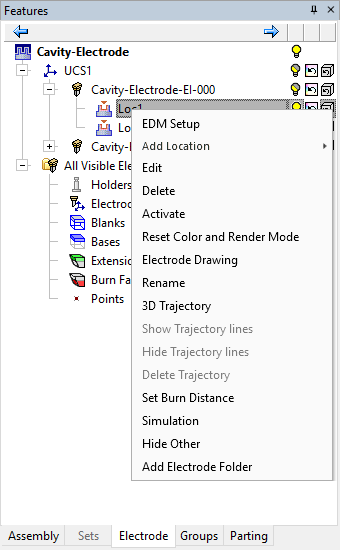
LocationLocation ![]() : This level represents the locations of each electrode. If an electrode appears more than once in the assembly, it will have several locations.
: This level represents the locations of each electrode. If an electrode appears more than once in the assembly, it will have several locations.
EDM Setup, Add Location, EditEdit, DeleteDelete, ActivateActivate, Reset Color and Render Mode, Electrode Drawing, RenameRename, Remove From FolderRemove From Folder, 3D Trajectory, Hide/Show Trajectory LinesHide/Show Trajectory Lines, Delete TrajectoryDelete Trajectory, Set Burn Distance, Simulation, Hide Other, Add Electrode Folder.
Picking multiple entities
Operations on multiple entities in the tree can be performed. If the entities selected are of the same level (locations, electrodes, etc.), the operations that can be performed are Hide, Show, Create Electrode Drawing, Create Assembly Drawing, All Drawings and Simulation (all appear under the popup menu). If the entities selected are not of the same level, only Hide, Show and Simulation are available.
For example:
-
Select multiple electrodes from the Electrode Tree:
-
Select All Drawings from the popup submenu.
All drawings will be created for the selected electrodes.
Set Burn Distance
Set the motion distance for each electrode location (without setting a 3D Trajectory).
This function can be invoked by right-clicking in the Electrode Tree on one of the following locations: UCS ![]() , Electrode
, Electrode ![]() or Location
or Location ![]() , and selecting Set Burn Distance in the popup menu. If the function is invoked from a UCS or Electrode, all their children are also selected.
, and selecting Set Burn Distance in the popup menu. If the function is invoked from a UCS or Electrode, all their children are also selected.
The Set Burn Distance dialog is displayed:
Set the required burn distance by selecting the appropriate option:
|
Use default distance |
This option displays the minimum extraction distance (taking into account the electrode direction and the burning faces). This value is grayed out and cannot be changed. |
|
Set burn distance |
Set the burn distance as required. The value must be equal to or greater than zero. If the value is smaller than that of the default distance, the text inside the box is displayed in red. When invoking this function from multiple UCSs, Electrodes or Locations, the following occurs:
|
Interaction with other functions
The Set Burn Distance function interacts with the following functions:
|
If an electrode has a defined distance, the simulation will move it to that distance. |
|
|
If you define a 3D Trajectory, it overrides the defined distance in the simulation. If you use the Set Burn Distance function and one or more selected locations has a 3D Trajectory defined, a message is displayed informing you that a 3D Trajectory has been defined and prompting you to delete the 3D Trajectory for the defined burn distance to take effect. |
|
|
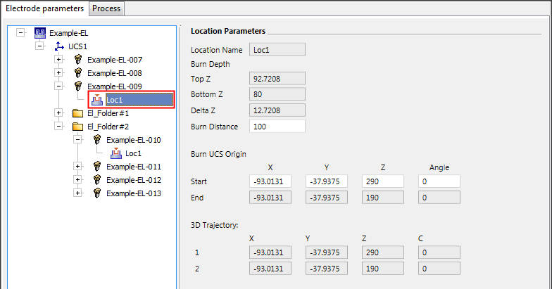
The burn distance is also shown in the EDM Setup.
Any changes works both ways: The Start Point and Burn Distance in the EDM Setup interacts with the defined distance (any change in the Tree will affect the values in the EDM Setup). If you change the Burn Distance in the EDM Setup, it will affect the Set Burn Distance value (in the Tree). In addition, a change in the Burn Distance is reflected the Start Point XYZ coordinates in the EDM Setup (for this location). If you change the Start Point, the Burn distance is updated respectively (in the EDM Setup and the Tree). If a 3D Trajectory is defined for a specific location, the last two coordinates of the trajectory are the Start and End coordinates respectively. The Burn Distance (the last motion) is also updated accordingly. Notifications If any of the start point, end point and distance values is different than the automatically calculated value, it is marked with a blue icon. Press this icon to reset the default distance, if required. If the user-defined distance is smaller than the automatically calculated distance, its text is colored red. |
|
|
When adding a location, the parameter of the location that was right clicked before the Add, will be copied to the new location(s). When adding an external electrode, it will not come with this parameter since it is kept on the instance and not on the electrode itself. |
|