|
|
Show/Hide Add Parameters
Access: Right-click on a sub-assembly, folder, a component in the Assembly Tree, or on a component in the Graphics Area to display the popup and select Show/Hide Add Parameters. This displays the offset parameters. Subsequent selection of this option hides or shows these parameters.
The offset parameters can also displayed by double-clicking on a Connect feature or on an Add assembly feature.
Show or Hide the offset parameters of an assembly Connect or Add operation. This option switches display of the parameters; click to hide or display the parameters, depending on the current visibility of the parameters. When these parameters are displayed, they can be edited. For more, see Edit Parameters.
Note: The UCS Connect operation can only be edited if the connect type is UCS to UCS, UCS to Face, or UCS to Cone Face
You can only edit the parameters of connects listed under the part in the tree. For example: applying Show/Hide Add Parameters on a plate does not show the parameters of the screws that are connected to that plate, only the connect under the plate in the tree.
All relevant connect features under the selected part are shown.
Note: If you attempt to Show/Hide Add Parameters on a part without Connect/Add Sketch parameters, or if you double-click on connect types other than those mentioned above, an alert informs you there are no parameters to edit.
Example
Use Show/Hide Parameters to edit the offset parameters:
-
Open Show/Hide Add Parameters.
-
With the parameters displayed, pick and edit the appropriate parameters (the interaction is the same as for Edit Parameters).
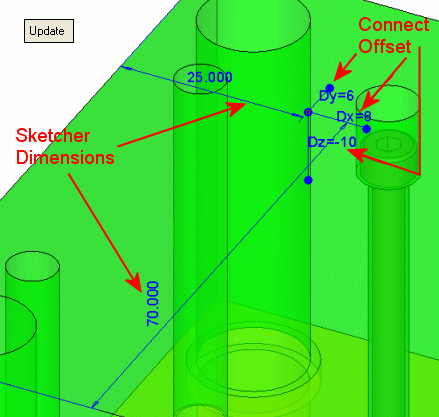
When invoking the Show/Hide Add Parameters on a Connect, the following dimensions are displayed:-
If you double-click on a Connect feature, the 3 offsets of the Connect feature are displayed (Dx, Dy, and Dz).
-
If a sketch is used and you double-click an Add feature or use Show/Hide Add Parameters, the sketch dimensions used to place the specific part (only if they exist) and the Dz offset are displayed.
Note: If components were added using a sketch, the Dx and Dy offsets are irrelevant.
-
If a sketch was not used and you double-click on an Add feature or use Show/Hide Add Parameters, the 3 offsets (Dx, Dy, and Dz) are displayed.

-
Each dimension shows the value inside the Connect feature and/or the Sketcher.
- The offset dimensions refer to the reference UCS of the connect feature.
- The sketch dimensions refer to the sketch point/circle.
The dimensions are displayed until you <exit><exit>. This is used to display the add parameters of several components simultaneously (because the Add parameters of a former component will not be hidden when the Add parameters of a new component are displayed).
|
