|
|
Connect Component 


Access: Open this function from one of the following locations:
-
Click the
button in the toolbar. -
Select Assembly > Main Tools > Connect from the menu bar.
-
Select Assembly > Tools > Connect from the menu bar.
-
Select Connect on the Graphics Area popup menu.
Create connections between components by defining constraints.
The connect process is used to orient components with respect to each other in an assembly. The components are positioned by using constraints, which relate the entities of the components, such as edges, faces and vertices, to each other.
Each component in an assembly has six degrees of freedom. It can move along the X, Y, and Z axes (translational freedom) and it can also rotate around these axes (rotational freedom).
Constraints remove degrees of freedom between two selected components, positioning them relative to one another. As you add subsequent parts, you add constraints to position the new parts relative to the other assembled parts.
The constraints that are available (and the selected default) depend on the types of geometry selected for the connect operation. For example, the Concentric constraint is not available for face to face connects and, of the available options, the Coincident constraint is automatically selected, by default.
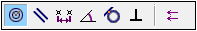
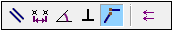
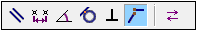
For example, depending on the types of geometry selected, the following constraints may be displayed:
|
Face to Edge |
Edge to Edge |
Face to Face |
Edge to Face |
|
|
|
|
|
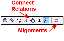
There are two kinds of constraints, translational and rotational.
Translational constraints have to be defined no matter which component entities are selected, edges, faces, vertices, etc. There are two kinds of translational constraints: Connect Relations (Angle, Coincident, Concentric, Distance, Parallel, Perpendicular and Tangent) and Alignments (Align and Anti-Align).
Rotational constraints are possible (as an optional step) only if you position a component specific UCS (User Coordinate System) to another component specific UCS.
Connecting Components
This image shows the Feature Guide for Connect Component.
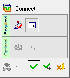
Required Step 1 ![]()
Pick the component entities to be connected. Pick two points, edges, faces, planes, axes or UCSs and then <exit><exit>. If you select a second entity from the same component, your second selection will replace the first.
Required Step 2 ![]()
Set the connection options by defining constraints. Each connect constraint is valid for a specific type of geometry. Only those constraints that are valid for the selected components are available.
Optional Step 1 ![]()
Set the coordinate system rotation parameters. This option is only available when positioning a component specific UCS (User Coordinate System) to another component specific UCS, or a face or plane.
Optional Step 2 ![]()
Pick the UCS origin. This option is only available when positioning a component specific UCS (User Coordinate System) to another component specific UCS, or a face or plane or cone face.
Detailed Interaction
See Options and Results.
|