Sketcher Dimension Dialog

Access: The Sketcher Dimension dialog is displayed in either of the following cases:
-
When you first assign a dimension.
-
Whenever you double-click on a dimension value (either in Select
 mode or Dimension
 mode).
The Sketcher Dimension dialog operates in a manner that is very similar to that of the Edit Parameters dialog, and enables you to change a dimension value. This can entail:
- Interactively modify actual dimensions of entities
- Defining an expression - internalinternal or externalexternal
- Relating Setup Parameters in an expression
- Defining Leading Dimensions
- Delete dimensions
When editing numerical values of a feature, clicking on the dimension opens the Sketcher Dimension dialog.
|
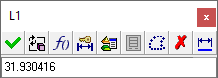
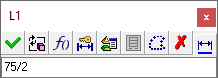
The default dialog size (collapsed). This is displayed for a dimension value or for simple expressions using arithmetic symbols that indicate the value.
The dialog is displayed expanded if the picked dimension already contains an expression or The expanded dialog is displayed if you press
|
See:
|
Dimension Dialog Structure
The structure of the dialog is as follows:
|
Header |
The dialog header displays: the name of the feature that owns the dimension (for example, Sketcher14). the dimension name (for example, L1).
|
||||
|
Top X Button |
The X button in the dialog title bar closes the dialog without saving any changes. |
||||
|
Buttons |
See the Dialog Buttons section below. |
||||
|
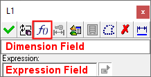
Dimension Field |
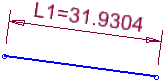
This field contains the numeric value of a dimension. The dimension field is numeric and shows the nominal/resultant dimension. The dialog displays the exact value of a dimension, while the corresponding dimension in the graphics window displays a rounded value, based on the number of decimal places.
Simple expressions using arithmetic symbols, may be entered in this
field, as shown:
In this case, only the result is kept (the number 37.5 will be shown in the dimension field the next time the dialog is opened).
|
||||
|
Other Fields |
Additional fields are displayed when the
Create Relation button See the Dialog Buttons section below. |
Note: The dialog can be resized by dragging the sides or corners.
ExampleExample:
|
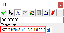
Default sized dialog - in this case, some of the expression is hidden: |
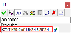
Horizontally resized dialog - the whole expression can be seen: |
|
|
|
Dialog Buttons
You can either enter a new dimension value in the dialog and close it, or click one of the buttons for further options.
The following buttons are in the dialog
|
|
OK: Accept the changes, perform the operation, and close the current dialog/task. This updates the geometry
according to the modified dimension value and exits the dialog.
|
||||||||||
|
|
Update: This updates the geometry according to the modified dimension value and remains in the dialog. |
||||||||||
|
|
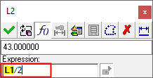
Create Relation: This toggle button enables you to create expressions (formulas) to define relations between dimensions. This option expands the dialog displaying additional fields, including an expression field which enables the creation of expressions. When you are creating an expression for the first time, the value in the expression field is initially the same as the value in the dimension field. The expanded dialog is
displayed either if you press the Enter an algebraic equation for the dimension, either containing numbers only or based upon other dimensions. See Parametric Dependency. Dimensions that are the
result of an expression, have the suffix (f);
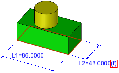
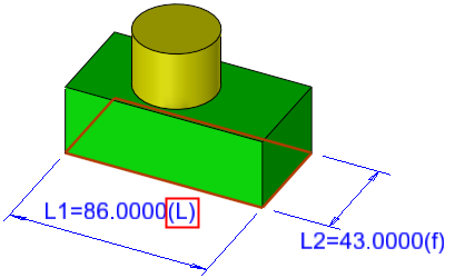
for example: In the example below, the dimension L2 is defined as being half the dimension L1. To include a dimension name in an expression, either enter it manually or just click the required dimension. When a reference dimension is added to an expression in the dialog, its ID appears in the expression field as bold text with a colored background, as shown below with the ID L1.
The expanded dialog displays the following additional fieldsfollowing additional fields:
By using formulas to relate a dimension to other dimensions in the same sketch, you can reduce the amount of editing that a part will need, and also assure that your design intent will be preserved. The driving dimensions can be tagged as leading dimensions and linked to the main setup table. Note: Formula based dimensions in sketches will be saved when possible—Formulae that relate to data within the sketch will be preserved; Linked data that is embedded in Setup or to components outside the sketch, such as dimensions in another sketch, may be lost if the related items are not present when the sketch is used, such as if a sketch is used in a new file. Notes:
|
||||||||||
|
|
Mark as Leading Dimension: This toggle button marks/unmarks dimensions to be tagged as leading dimensions. Dimensions that have been
marked as
Leading Dimensions have the suffix (L);
for example:
A leading dimension is any dimension that you define as such. Generally, leading dimensions are the main dimensions of a part, such as one that some other dimensions are dependent upon. For example, when adding relations between dimensions, the driving dimensions can be tagged as the leading dimensions.
|
||||||||||
|
|
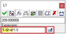
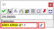
From Setup Table: When creating expressions to define relations between dimensions, dimensions can be selected from an external source (these are Setup dimensions).This option is used for displaying and selecting setup dimensions to enter them into the expression. |
||||||||||
|
|
Catalog Table:
This button invokes the catalog
table and is used for editing the parameters of catalog parts,
or for displaying and selecting catalog dimensions to enter them into
the expression. This option is dimmed in the Sketcher Dimension dialog. |
||||||||||
|
|
Turn to Reference: This toggle button turns one or more regular sketcher entities (lines and/or dimensions) into Reference Entities and vice versa. |
||||||||||
|
|
Delete: Delete the selected item. This deletes the dimension and closes the dialog. |
||||||||||
|
|
Turn Dimension to PMI: This takes dimensions created in the Sketcher or in features and turns them into PMIs (Product and Manufacturing Information). This may be used both in the Model, and in getting these PMIs later in Drafting. The created PMI is associated to the source dimension, so that if it changes, so does the PMI. If the source dimension is deleted, the associated PMI is also deleted. |
||||||||||