|
|
Feature Based Machining
In Cimatron, Feature Based Machining (FBM) (also known as Manufacturing Feature Recognition (MFR)) is a set of capabilities used to quickly, easily, and safely program plate machining with many features. It includes feature recognition and management tools for holes, pockets and chamfers, use of sequences and pocket templates for greater automation and shop floor standardization.
Specifically, it includes capabilities to simplify the programming, using dedicated automation tools. These capabilities include: feature recognition and management tools for holes, pockets and chamfers, pocket templates for milling automation including capping of sockets, automated facing procedures and chamfering procedures including detection of imaginary chamfers and holder collision prevention.
Uses of Feature Based Machining include:
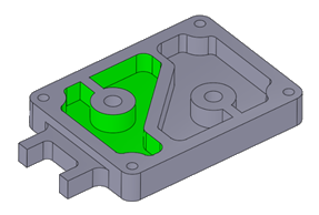
Pocket Recognition
Recognition of all pockets in a Plate is a preliminary step for automating the process of pocket machining.
The recognized pockets can be used in downstream procedures and templates. The relevant geometry from the Pocket feature is automatically selected by the procedure. For example, the Volume Pocket procedure takes the pocket’s volume, the Finish procedures take the surfaces and the Profile procedures (Profile Closed Contour and Profile Open Contour) take the contours and Z values.
For more see Pocket Manager.
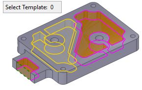
Templates for Pocket Milling Automation
Templates for Pockets is a Feature Based Machining function enabling faster, safer and simpler programming for milling multiple pockets. In many cases, pocket milling requires similar sequences of NC procedures. These sequences contain for example, roughing, wall finishing, floor finishing, cleanup, chamfering, etc.
When a job requires the milling of multiple pockets, the programming may take time and this increases the possibility of human error.
Define and create a Template by selecting any sequence of procedures. Once a Template is defined, you can apply it on any pocket feature. Usage of Templates enables you to apply a complete milling process to all pocket features in a single operation, saving programming time and preventing user errors.
For more see Apply Templates for NC Pockets.
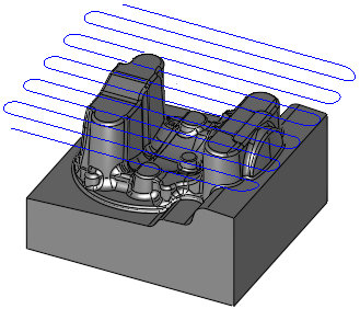
Facing Procedure Automation
For more see 2.5 Axes Facing - Contour Cutting
Chamfer Procedure Automation: Chamfer Open Contour and Chamfer Closed Contour
Automatically detect sharp edges as candidates for chamfering ("Imaginary" chamfers) as well as "Designed" chamfers, based on parameter settings. The detected geometry is then automatically used as input for the chamfering toolpath.
The Chamfer Detect option is displayed for the procedures: Chamfer Open Contour and Chamfer Closed Contour.
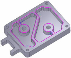
Automatic Capping of Socket Areas in Pocket
Capping drilled holes or gaps in pocket floors is a Feature Based Machining function enabling smoother tool motions.
Pockets may contain existing socket areas (e.g. holes, slots) on their bottom floor. Milling pockets without capping these holes, may result in inefficient tool motions interrupted by going around the holes. Capping these holes produces smoother tool motions.
Before generating a toolpath, these bottom floor socket areas can be capped using one of the following options:
For more, see Geometric Pockets Floor Capping.
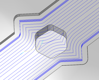
The image shows a capped hole on a pocket floor, allowing smoother tool motions.
|