|
|
Simple View Projection Type 

![]()
![]()
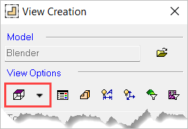
Access: A view is created under the currently active sheetactive sheet (either double-click the sheet name ![]() in the Drawing Tree or right-click it and select Activate Sheet). The View Creation dialog can be accessed using one of the following methods:
in the Drawing Tree or right-click it and select Activate Sheet). The View Creation dialog can be accessed using one of the following methods:
-
Click
in the toolbar. -
Right-click the currently active Sheet item
 in the Drawing Tree and select View Creation.
 -
Right-click the graphics area and select View Creation.
-
Select Views > View Creation > View Creation from the Drafting menu bar.
Define the projection of the view as it is displayed on the sheet.
Defining the view projection
InvokeInvoke the View Creation function.
Click Simple View Projection Type ![]() in the View Creation dialog.
in the View Creation dialog.
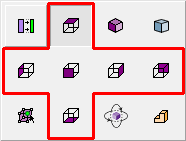
The Simple View Projection Type options are displayed.
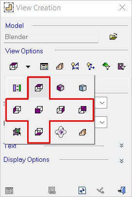
Select the appropriate view (see Example views below for more information).
|
|
|
|
|
|
|
|
|
|
|
|
|
|
|
|
|


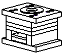
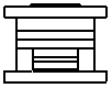
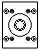
Example views
Bottom
|
D-View (M-View)
|
Derived or Auxiliary
|
Diametric
|
Front
|
Interactive
|
|
|
|
|
ISO
|
Left
|
Multi-ISO
|
|
|
|
|
Rear
|
Right
|
Top
|
|
|
|
|
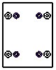


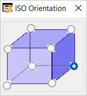

Interactive view
Select Interactive ![]() to define the orientation of the view. This option provides unlimited control by allowing you to dynamically rotate the part on the drafting sheet. To ensure clarity, the view is shaded while in Interactive mode, but the end result will be displayed according to the View Attribute settings. When this option is selected, the following dialog is displayed.
to define the orientation of the view. This option provides unlimited control by allowing you to dynamically rotate the part on the drafting sheet. To ensure clarity, the view is shaded while in Interactive mode, but the end result will be displayed according to the View Attribute settings. When this option is selected, the following dialog is displayed.
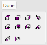
Either rotate the model to the desired orientation or select one of the orientations from the adjacent set of buttons that perform the operation without changing the zoom. These icons are similar to those shown in the Example views section above, with the exception of the following ISO orientation buttons.
|
|
Display the ISO top view. |
|
|
Display the ISO bottom view. |


In addition to the basic set of orientations (in the top two rows of buttons), the following options are also available:
|
|
Rotate to plane Rotate to a picked plane or planar face. |
|
|
Rotate by angle Rotate the view by a defined angle. Rotate each axis by a defined angle. The Rotate dialog is displayed.
|


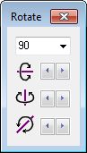
Click Done when finished.
|