|
|
Geometrical Tolerance 
![]()
![]()
Access: Open this function from one of the following locations:
-
Click the
button in the toolbar. -
Select Symbols > GD&T > Geometrical Tolerance from the menu bar.
-
Select Drafting Symbols > Geometrical Tolerance from the popup menu (right-click the Graphics Pane area).
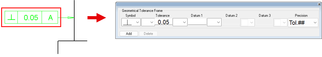
Add a geometric tolerance to the drawing. Geometric tolerances are used to control form, profile, orientation, location and runout.
|
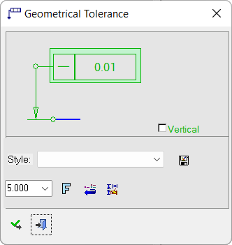
The Geometrical Tolerance dialog displays
|
Below is an example of the symbol.
See Entity Overview for a general description. |
Creating a Geometrical Tolerance
-
InvokeInvoke the Geometrical Tolerance function.
-
Pick the location of the geometric tolerance start point.
-
Pick a point in the graphics display area (Graphics Pane) to position the geometric tolerance and exitexit.
-
Pick a point on the screen to define the new position of the entity (the entity will jump to the picked point).
-
Double-click the entity and edit it with the help of the hot spots and tips either directly in the graphics display area or on the popup submenu, then open the Geometrical Tolerance Frame to edit its parameters.
-
To complete the current operation and remain in the dialog, press the Apply
 button or exitexit.
To exit the function, press the Close button.
Notes:
-
Right-click the entity itself to access the entity-specific (for editing) and general functions from the popup submenu.
-
Double-click the entity to edit it.
-
Creating a PMI geometrical tolerance symbol (in the Modeling environment) is very similar to creating a geometrical tolerance symbol in the Drafting environment, even though modeling is a 3D environment and drawing is a 2D environment.
-
See the Symbol notes for additional information.
Attaching Geometrical Tolerance frames to Linear and Radial dimensions
Linear dimension
You can attach a Geometrical Tolerance frame directly to a Linear dimension with an end point drag operation. When attached, the Geometrical Tolerance frame can be moved independently of the Linear dimension; however, if the Linear dimension is moved, the Geometrical Tolerance frame will move with it. To unattach the frame, use the same end point drag operation you used to attach it.
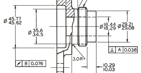
Radial dimension
Geometrical Tolerance frames can also be applied to Radial dimensions (at the center of the dimension's leader) using the end point drag operation. When attached, the Geometrical Tolerance frame can be moved independently of the Radial dimension; however, if the Radial dimension is moved, the Geometrical Tolerance frame will move with it. To unattach the frame, use the same end point drag operation you used to attach it.
|