|
|
Selecting Geometry by Criteria

While selecting contours or surfaces, right-click to open the popup submenu:
|
While selecting contours from Contour Manager dialog (under the Selection Method section of the dialog): |
While selecting surfaces: |
|
|
|
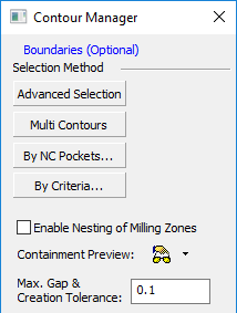
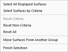
From either popup submenu, choose By Criteria to open the Criteria Dialog.
The Criteria selection mode in NC is very similar to the Criteria selection mode in the CAD environment. When picking geometry for a procedure, you can use Criteria to automatically select all entities that meet a certain profile. These criteria include: color, entity, line style, line width, and sets.
For examples of the Criteria selection dialog displayed in the NC environment (the Sets - Create and Edit dialog), see By Criteria Selection.
For an example of the use of criteria selection in the NC environment, see the selection by criteria example below for the Automated Drill procedure.
Note: the Selection Filter can also be used to select geometry that meets a certain profile. However, the Selection Filter can only be used while manually selecting entities. A selection by criteria automatically includes all entities meeting a profile.
If a procedure contains geometry selected by criteria, it will have a "c" status symbol next to the status flag (i.e.  ). If geometry that has been selected by criteria is changed, the procedure will have a geometry change status symbol next to the status flag (i.e.
  ).
).
In addition, in the Geometry Parameter Table, you can see how many of each geometric entity were selected manually and by criteria:
Criteria groups can be defined using OR logic (geometry that fits any given criteria) or AND logic (geometry that fits all given criteria).
Selection by Criteria Example (Automated Drill)
In the Automated Drill function, for example, selecting geometry by criteria enables you to easily select the area of the mold containing the holes that you wish to drill. You can select the area either by:
its geometry, or
other criteria, such as color or set. This can be of particular use when importing colored geometry into Cimatron that has not been fully defined.
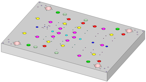
For example, the colors of the holes in the plate below are according to a customer’s standard. Each color represents a different hole type. In this case, the yellow, purple and red holes are all have a diameter of 18 mm.
However, each color represents a different drilling process:
-
Yellow holes: Standard holes.
-
Red holes: Accurate location.
-
Purple holes: Accurate location and accurate diameter.
In Cimatron, it is possible to automatically define different automated drill procedures for each group by using the color criteria selection.
|