Process Manager: Status Flags & Symbols

Access: Open this function from one of the following locations:
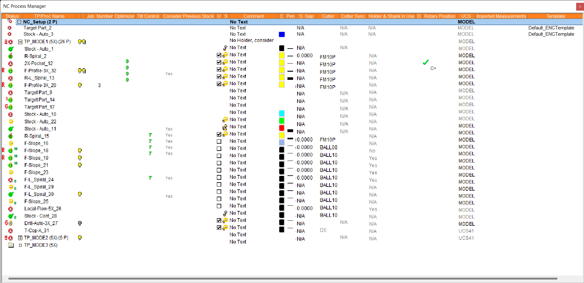
The NC Process Manager consists of a collapsible tree containing detailed information of all toolpaths and their procedures. In addition, the Process Manager displays the status of each toolpath and procedure by using status flags and symbols.
Multiple Selection in the NC Process Manager
-
Non-Consecutive Selection: To select non-consecutive entries, use the Shift key together with the left mouse button.
-
Consecutive Selection: To select consecutive entries, click and hold down the left mouse button while dragging; there is no need to use the Shift or Ctrl keys. If you keep dragging past the window, the procedure list will scroll. When several procedures are selected, you can right-click the mouse to access options such as Delete or Comment for the entire selection. If you click/hold/drag the left mouse button when directly over the Process Manager light bulb icons, you can quickly hide or show many procedures on the screen at once.
In the Process Manager, each toolpath and procedure is marked with a flag to reflect its current status. In addition to the flags themselves, letters or symbols may appear next to the flags to give you a further indication of the status.
The flags indicate whether the toolpath or procedure has been calculated, suspended, interrupted, or is potentially problematic. Symbols located to the left of a flag are colored RED, indicating problems associated with input to the procedure. Symbols located to the right of a flag are colored GREEN and are more informative in nature.
Status Flags
In the Process Manager, each toolpath and procedure is marked with a flag to reflect its current status. The flags are as follows:
|
|
Toolpath: The toolpath contains only calculated procedures. Executed (cutter motions exist), ready for post-processing. A toolpath folder is marked with the If a toolpath contains procedures with a higher priority status flag, that flag will be applied to the toolpath.
A procedure is marked with the
|
||||||||||||
|
|
Toolpath: The toolpath contains suspended procedures. The procedure is ready for execution, however, it is suspended for some reason (for example, because the cutter was changed or because no cutter motions exist yet in the procedure). A toolpath folder is marked with the If a toolpath contains procedures with a higher priority status flag, that flag will be applied to the toolpath. A procedure is marked with the A procedure is marked with the
|
||||||||||||
|
|
Toolpath/Procedure: Interrupted by the application or by the user. Additional information about this flagAdditional information about this flag A procedure is marked with the If a toolpath contains procedures with a higher priority status flag, that flag will be applied to the toolpath. If an interrupted procedure contains motions, the hide/show bulb is displayed.
|
||||||||||||
|
|
Toolpath: The toolpath contains problematic procedures. Cutter motions have been calculated and the procedure can be sent for post processing, but it is recommended to check and re-execute the procedure. This flag can be caused by procedure interruption, optimization, etc. A toolpath folder is marked with the If a toolpath contains procedures with a higher priority status flag, that flag will be applied to the toolpath. A procedure is marked with the
|
||||||||||||
|
|
Toolpath: Not ready for calculation, procedures in different statuses. The toolpath/procedure is not ready for execution, or geometry has been deleted. The toolpath folder is marked with the If a toolpath folder contains procedures with different status flags & symbols including the When a procedure is created and the required input data is still missing, the procedure is marked with the
|
||||||||||||
|
|
Procedure: Background calculation. The procedure is currently being calculated (executed) in the background. A procedure is marked with the Procedure flags and symbols are only updated when the calculation is completed and not during the calculation process. If multiple procedures are sent to background calculation, each procedure is updated when its calculation is completed and not by its position in the procedure list. A procedure cannot be selected during the calculation process. If a procedure (for example procedure A) influences a procedure under background calculation (for example procedure B), the status flag of procedure A changes using the same general rules as other procedures located in Process Manager.
|
||||||||||||
|
|
Toolpath: Empty toolpath. The toolpath does not contain any procedures. |
||||||||||||
|
|
Toolpath/Procedure hidden: A status flag with a gray background indicates that the toolpath or procedure has been hidden. |

 or
or  or
or  or
or  , with


 ).
).
Status Symbols
In addition to the status flags, Symbols may appear in the Process Manager to give you a further indication of the status of a toolpath or procedure.
The appearance of symbols in the Process Manager, conforms to the following:
-
Symbols may be displayed next to a status flag and may appear on either side of the flag:
-
-
Symbols located on the left of a flag are colored Red and indicate problems associated with input to the procedure (such as geometrical or stock problems).
-
Symbols located on the right of a flag are colored GREEN and are more informative in nature (for example, to indicate the usage of special mechanisms in the procedure, such as the Motion Editor, Criteria selection, etc.).
-
-
The
 and
and  symbols may also be displayed in the Process Manager, where appropriate.
The following symbols may be displayed on the left of the status flag:
|
D |
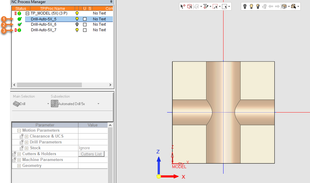
This symbol indicates that a previous AutoDrill or Drill procedure has changed and that the current procedure may need to be recalculated. This symbol can be cleared manually if required. Additional information about this symbolAdditional information about this symbol When an AutoDrill procedure includes a sequence with Gun Drilling with intersection control enabled, the process defines an intersection as a part of the hole, which has been previously drilled either by the current procedure or by a previous Drill or AutoDrill procedure in the process. Therefore, if a previous procedure is modified or re-executed, it is possible that the intersection values of the Gun Drilling sequence have been changed. In this case, the AutoDrill procedure with the Gun Drilling sequence will receive a D symbol to notify that it should also be re-executed. If a procedure with a D symbol is executed, the D symbol will be removed. A procedure with a D symbol may be reported, posted, and navigated. Procedure 1 drills the horizontal hole. Procedure 2 drills the vertifical hole with Gun Drilling but not intersection control. Procedure 3 drills the vertical hole with Gun Drilling with intersection control. Therefore, after re-executing Procedure 1 (as shown in the image below), only Procedure 3 receives the D symbol.
|
||||||
|
|
This indicates that the remaining stock has been modified for some reason. As Cimatron tracks the remaining stock, the stock model that was used when the procedure was originally calculated has now changed. The R flag indicates that you should recalculate these procedures. However, this symbol can be cleared manually if required (if you decide that the change to the stock is not significant enough to require recalculation). A procedure with the If a procedure with the A procedure with the If a procedure with the If a procedure is suspended ( If the calculation of a suspended procedure ( If it contains a toolpath, a procedure with the
|
||||||
|
|
This indicates that the procedure geometry has changed or that the part file that was loaded into the NC file was updated. In this case, the geometry needs to be redefined. See Update Mode and Switch to CAD & then CAM Mode. A procedure with the If a procedure is suspended ( If a procedure is created but not executed because all the required information was not supplied (ie. the A procedure with the If it contains a toolpath, a procedure with the
|
||||||
|
r |
For the Automated Drill procedure; this indicates that the group's stock (maybe for only some of the holes) has changed but it is within the range defined for the sequence. This flag is informative only, no user interaction is required. |
||||||
|
|
This indicates that the procedure geometry has changed, or that the part file that was loaded into the NC file was updated. In this case, the geometry does not need to be redefined. See Switch to CAD & then CAM Mode. A procedure with the If a procedure is suspended ( If a procedure is created but not executed because all the required information was not supplied (ie. the If it contains a toolpath, a procedure with the
|
||||||
|
* |
This indicates that there is a discrepancy between data. An appropriate popup message is displayed when hovering above a flag with this symbol. This may occur, for example, in the following cases: A discrepancy between the Cutter Compensation defined in the Preferences and that defined in the procedure. A discrepancy between Coolant values in the Preferences and the values saved in the procedure, or if a template with different settings is loaded.
When trying to Post Process or Machine Simulate a procedure with the * flag, a message is displayed that the G-Code cannot be created as a value (Cutter Compensation, Coolant, etc.) in at least one of the selected procedure(s) contradicts the type defined in the Preferences. |
||||||
|
|
These red bars are only displayed at the toolpath level together with a status flag (eg.
|
 symbol means that the procedure was already executed when the remaining stock was, for some reason, modified. In such a case the existing toolpath is not changed but the
  flag.
flag. symbol means that the procedure was already created and/or executed when the selected geometry was, for some reason, modified, moved or deleted. In such a case the existing toolpath is not changed but the
  flag.
flag. ).
).
 symbol
 flag
flag
 ) and indicate that a toolpath is not ready for execution as its procedures are at different statuses (more than one kind of status flag (other than
The following symbols may be displayed on the right of the status flag:
|
M |
This indicates that an operation was performed on the procedure using the Motion Editor. A procedure with the The If it contains a toolpath, a procedure with the
|
|
c |
This indicates that the geometry selection was done by Criteria. A procedure with the The If geometry that has been selected by criteria is changed, the
|
 symbol means that an operation was performed on a calculated toolpath using the Motion Editor. In such a case the
  flag.
flag. symbol means that the geometry for this procedure was selected using criteria.
 ) even if only one entity was selected using criteria.
The and symbols may also be displayed in the Process Manager, where appropriate.
|
|
This symbol is displayed in the Optimizer column in the Process Manager and indicates that the optimizer mechanism was used on this procedure. A procedure with the The If it contains a toolpath, a procedure with the
|
|
|
This symbol is displayed in the Tilt Control column in the Process Manager and indicates that the tilting mechanism (5-axis inclination) was used on this procedure. A procedure with the The If it contains a toolpath, a procedure with the
|
Examples
The following examples show some of the status flag and symbol combinations:
|
|
The procedure was already executed when the remaining stock was, for some reason, modified. |
|
|
The procedure geometry has changed or the part file used during Load Model was updated. In this case, the geometry needs to be redefined. See Update Mode. |
|
|
The procedure geometry has changed or the part file used during Load Model was updated. In this case, the geometry does not need to be redefined. |
|
|
The procedure was manually edited using the Motions Editor. |
|
|
Criteria was used for geometry selection. |
|
|
As explained for |
|
|
As explained for |
