|
|
Geometry Parameters Table
The Geometry Parameters define the geometrical entities to be used during the procedure operation.
For a parameter description, click on a parameter in the dialog image below.
Depending on the procedure and your parameter settings, some parameters may not be available or other parameters may be displayed.
Click here for a complete list of parameters in this table.
|
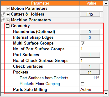
Example Geometry table (for Finish procedures): |
|
|
|
Specific parameters are displayed for certain procedures: |
General Notes about Parameter Tables
Notes:
-
You can use the Preferences to define colors for selected surfaces.
-
See the Surface Selection Options for details of how to move surfaces from one group to another.
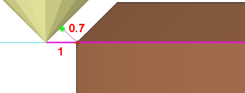
In 2.5 Axes Chamfer procedures, when defining offsets for contours and surfaces, note that:
Contour offset is a 2D offset.
Surface offset is a 3D offset.
In the image below, the contour is marked in purple. Note that the contour offset is defining as 1, while the surface offset is 0.7.
2.5 Axes > Slotting - Geometry Parameters
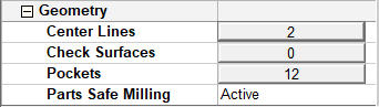
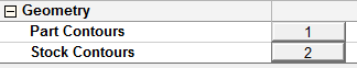
For the 2.5 Axes > Slotting procedure, the following type of Geometry table is displayed:
Clicking the Center Lines button displays the Contour Manager and enables the selection of center lines (skeleton) of pockets to define the slotting path.
A Center Line column is available in the Pocket Manager. This displays the visibility (hide/show) status of the center line (skeleton)
of a pocket.
|
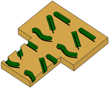
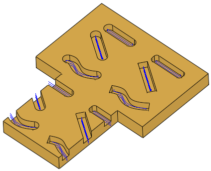
The Slotting procedure recognizes open and closed slot ends and displays the center line contours: |
The center line (skeleton) of the slot-shaped pockets are milled: |
|
|
|
Clicking the Pockets button displays the Pocket Manager.
A Slot Likelihood column is available in the Pocket Manager. This displays the likelihood that the pocket is a slot-shaped pocket, ranging
between zero (not a slot-shaped pocket) and 100 (definitely a slot-shaped
pocket).
Contours and Pockets Notes:
-
If more than one contour is selected, each contour is milled separately.
-
The center lines (skeletons) of all contours and pockets are calculated and converted to segments. If segments intersect, the system attempts to create the longest (main) segments.
-
The segments are machined one by one with the longest segment being milled first, then the order is defined by "go to closest".
-
A pocket is milled only after all pockets "above" it have already been milled. This is reflected in the Pocket Number in the Pocket Manager Table.
2.5 Axes > Volumill Pocket - Geometry Parameters
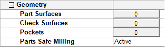
For the 2.5 Axes > Volumill Pocket procedure, the following type of Geometry table is displayed:
Drill > Automated Drill - Geometry Parameters
For the Automated Drill procedures, the following type of Geometry table is displayed:
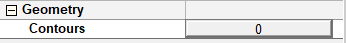
Remachine > Guided Cleanup/Multi Axes Guided Cleanup Geometry Parameters
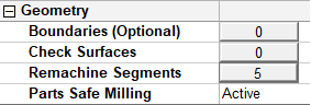
For the Guided Cleanup and Multi Axes Guided Cleanup procedures, the following types of Geometry tables are displayed:
| Guided Cleanup: | Multi Axes Guided Cleanup: |
 |
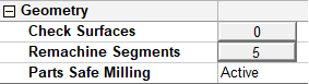 |
Geometry > Boundaries option: The input for the Guided Cleanup and Multi Axes Guided Cleanup procedures is generated from the Remachine Segments Table. The Remachine Segments option displays the number of segments selected and enables you to change the selecti
Geometry > Remachine Segments option: The input for the Guided Cleanup and Multi Axes Guided Cleanup procedures is generated from the Remachine Segments Table. The Remachine Segments option displays the number of segments selected and enables you to change the selection.
Transformation - Geometry Parameters
For the Transformation procedures, the following type of Geometry table may be displayed - depending on the Transformation subselection option (in the example below, the subselection Copy was selected):
![]()
Turning > Geometry Parameters
For the Turning procedures, the following types of Geometry table are displayed:
For a parameter description, click on a parameter in the dialog image below.
|
Lathe Drill procedure: |
||
|
|
|
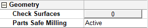
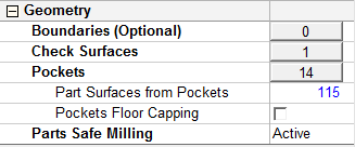
Volume Milling > Volume Pocket - Geometry Parameters
For the Volume Pocket procedure, the following type of Geometry table is displayed:
For a parameter description, click on a parameter in the dialog image below.
Notes:
-
To pick geometry for a procedure, either press the
 button in the Work Mode Dialog (if you are in Wizard Mode), or display the Geometry parameters in the parameter tables.
 -
When picking geometry for purposes other than those essential for executing a procedure (for example, picking surfaces to change their color), use the Selection Filter.
|