Grid Settings

Access: Open this function from the following location:

  • Select View > Grid & Snap > Grid & Snap Settings from the menu bar.

Turn Grid & Snap ON or OFF (for use in the Sketcher). Grid & Snap enables more precision in sketching and positioning elements in the graphics area.

Set the parameters for the Grid & Snap function.

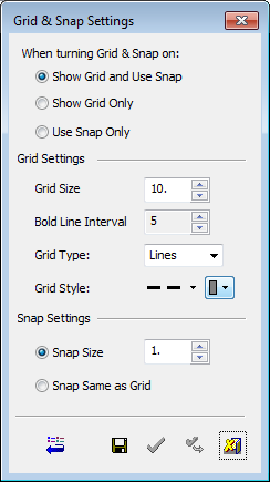
The grid and snap parameters are defined in the Grid Settings dialog. These include the grid display type (lines or points), color, spacing and snap point locations.

The Grid Settings dialog is displayed:

Set the parameters as required.

See the explanation of the dialog buttons.

Set the parameters:

Grid Size

Display the grid and use the snap.
This is the default option.

Bold Line Interval

Only display the grid, without using the snap.

Grid Type

The grid lines can be displayed using either dashed lines or dots.

Grid Style

Only use the snap, without displaying the grid.

When Turning Grid & Snap on

Select the type of functionality required from one of the following options:

Show Grid and use Snap

Display the grid and use the snap.
This is the default option.

Show Grid Only

Only display the grid, without using the snap.

Use Snap Only

Only use the snap, without displaying the grid.


Grid Settings

Set the following Grid parameters:

Grid Size

Sets the grid spacing to the specified value.

Bold Line Interval

The frequency of major lines compared to minor lines - a setting of '3' will display every 4th line as a bold line.

Grid Type

Select the type of grid to be displayed. The following options are available in the dropdown list:

Lines

Display the grid lines. The grid consists of major and minor lines. Major grid lines separate the grid into major units and are displayed as darker lines. Minor grid lines separate the units delineated by the major grid lines.
ExampleExample:


Points

Display the grid points. The grid points are displayed on the intersections of all the major and minor lines.
ExampleExample:


Grid Style

Select the grid line style and color from the appropriate dropdown list. The major and minor grid lines are the same style and color, with the major lines shown in bold.

If the grid type is points, then only the color option is relevant.

Grid Spacing

Set the major and minor grid spacing. The grid spacing starts from the active UCS of the sketch.

Major spacing

Set the major grid spacing in mm/inches.
ExampleExample:

In the example below, the major spacing is 100.


Minor per major

Set the minor grid spacing. This defines the number of equal divisions between major lines.
ExampleExample:

Minor spacing = 4

Minor spacing = 5


Snap Settings

Define the positions of the snap points. The following options are available:

Snap points per minor

Define the number of snap points per minor box.
ExampleExample:

1 = 1 snap point per minor box.

2 = 2 snap points per minor box.

0 = a snap point at every major intersection.


Snap delta

Define the snap points according to X and Y values. For example X = 75, Y = 100, means that the snap points occur every 75 mm on the X axis and every 100 mm on the Y axis.


Limits

Limit the area of the screen that is covered by the grid. The following options are available from the dropdown list:

On

Display the grid only on the reference sketch plane (on the gray area).
ExampleExample:

Off

Display the grid on the entire screen.
ExampleExample:


Grid Settings Buttons

Restore Defaults: Restore the system default settings to the dialog.

Save: Save the dialog settings.

OK: Accept the settings and exit the dialog.

Apply: Accept the settings and remain in the dialog.

Cancel: Reject the settings and exit the dialog. In this case, all changes since the dialog was opened, are cancelled.

Some functionality may be dependent on the product package. Contact your Reseller if you require a license.