|
|
Intersection Curve  : Options and Results


Access: Open this function from the following location:
-
Select Wireframe > Derived Curves > Intersection from the menu bar.
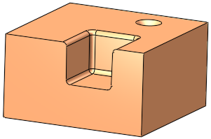
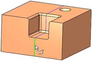
Create intersection curves between objects, faces, and planes.
This function is executed by selecting two groups: the first containing one or more faces and the second group containing one or more faces and/or planes. The result consists of all curves along all intersections of the two groups.
The two examples below demonstrate how to use this function.
Required Step 1 
-
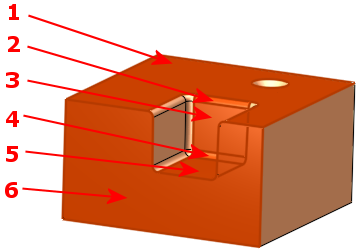
Pick the first group of one or more faces.
-
Click <Exit><Exit> to proceed to the next step.
|
|
|
Note: Closed and open mesh objects can also be picked. If an mesh object is selected, all previous selections of solid objects are cleared.
Required Step 2
-
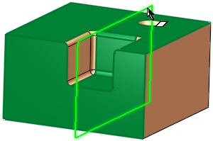
Pick the second group of one or more faces and / or planes. In this case, the second group is a vertical datum plane.
-
Set the parameters.
Note: If an mesh object was selected in Step 1, then the following entities can be picked:
-
Datum plane
-
Closed mesh object
Parameters
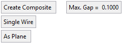
Create Composite / Don't Create Composite
Toggle this parameter to define the type of curve created by the function (see below for an example). When the Create Composite option is selected, the Max. Gap parameter is displayed.
Max. Gap
Enter the maximum gap tolerance allowed when creating the curve.
Examples of Composite CurveExamples of Composite Curve
When projecting a composite curve or a sketch (containing more than a single edge), the toggle option, Create Composite/Don't Create Composite, enables the result to either be a single composite curve or separate curves.
Create Composite
Don't Create Composite

Single Wire /
Multi WiresThis toggle option enables the creation of single or multiple wire bodies.
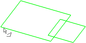
Single Wire
When numerous entities are selected, they are defined as a single wire (the group of entities is regarded as one entity). This is illustrated below where pointing to one of the wires (note the cursor symbol) highlights all the entities in the single wire.
Multi Wires
When numerous entities are selected, they are defined as a multiple wires (the group of entities is regarded as multiple entities). This is illustrated below where pointing to one of the wires (note the cursor symbol) highlights only the relevant entity.
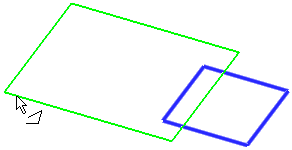
If Don't Create Composite is selected above, this option is grayed out and set to Multi Wires.
As Plane /
As FaceIf the picked face is planar, an additional toggle option is displayed: As Plane / As Face. This option enables you to define the second group as either a plane or face, which in turn may affect the size of the intersection curve.
-
-
Click OKOK
 or ApplyApply
 in the Feature Guide to complete the function.
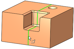
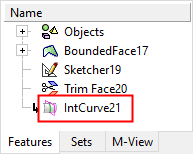
When completed, the Intersection Curve feature(s) will appear in the Feature Tree.

|