|
|
Lifter Pocket  : Options and Results
Access: Open this function from one of the following locations:
-
Select Mold Design > Lifter > Lifter Pocket from the menu bar.
-
Select Lifter > Lifter Pocket from the Mold Design Guide Toolbar.
Insert a cavity in the relevant active part(s) to make room for a lifter.
Create pockets for complex lifters.
Required Step 1 
Pick the lifter for which a pocket is required. The shape of the created pocket is the same shape as the lifter.
|
A target part and a lifter are selected. |
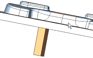
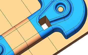
The pocket created in the target part has the shape of the selected lifter. |
|
|
|
The next step of the function is automatically invoked.
Required Step 2 
Pick the target part either from the graphics area or from the Assembly Tree. The target part is the active part to be cut by the lifter selected in the 1st step.
Pick either:
-
The target/stock part (the plate to be cut) either from the graphics area or from the Assembly Tree. The target part is the active part to be cut by the lifter selected in the 2nd step (using the Create Pocket in Selected Part toggle option).
-
The parting surface part. The pocket faces will be exported to this part in the 2nd step (using the Export Pocket Faces to Parting Surface Part toggle option).
The following parameters are displayed in the Lifter Pocket function:
|
Toggles to: |
||
|
|
|
|
Parameter descriptions:

|
Create Pocket in Selected Part |
This is a toggle option that enables you to select the target part (the part in which the pocket is to be created) from either an active part or in a parting surface part. The toggle options are Create Pocket in Selected Part / Export Pocket Faces to Parting Surface Part.
|
||||
|
Target Part |
This parameter displays the name of the selected component. This step requires that a target part be selected. This can be accomplished in a number of ways (see the options above); however, the interaction of the Target Part parameter is the similar for all the methods. The parameter is displayed in red when it is empty (before a part is picked or if you clear the selection). After a part has been picked, the parameter is grayed out and displays the name of the selected component. For example:
When the Create Pocket in Selected Part option is selected (above); the parameter is displayed in red until a part is selected, and then the parameter is grayed out and displays the name of the selected component. When the Export Pocket Faces to Parting Surface Part option is selected (above):
|
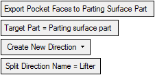
If the Export Pocket Faces to Parting Surface Part option is selected, the following additional parameters are selected:
|
Create New Direction |
This is a dropdown list of options that enables you to define whether the coincident faces (of the work part and the lifter) after they are split in the target part, are assigned to a new QuickSplit direction, to a selected direction or if they remain in the same direction.
|
||||||||
|
Use Lifter Body |
This is a toggle option Use Lifter Body / Use Cutting Object that enables you to choose how to create the pocket. This parameter is only available if a cutting object exists inside the lifter.
|
Press OK ![]() or Apply
or Apply ![]() in the Feature Guide to complete the function.
in the Feature Guide to complete the function.
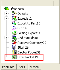
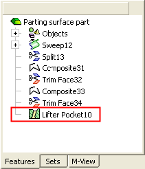
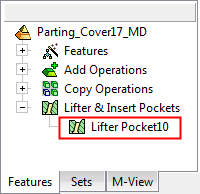
When completed, the Lifter Pocket feature will appear in the relevant assembly and part Feature Trees. This feature is created in the relevant part (stock or parting surface part) and also under the Lifter & Insert Pockets branch of the relevant assembly. See the examples below.
|
Feature created in the stock part: |
Feature created in the parting surface part: |
Feature created under the Lifter & Insert Pockets branch of the relevant assembly: |
|
|
|
|
|






 and picking a split face, or by selecting a split direction from the tree.

