|
|
Intermediate Curve  : Options and Results
Access: Open this function from the following location:
-
Select Wireframe > Derived Curves > Intermediate Curve from the menu bar.
Create one or more an intermediate curves between two curves. Any number of intermediate curves can be created. If 2 points are selected, the result is an intermediate point (or a number of points as required).
This function may be used, for example, to divide an angle, place components on a part, define the split direction, or to find a centerline for machining purposes (to guide the path or orientation of the tool during NC programming).
Required Step 1 
-
The following parameters are displayed (the geometrical entities in the images are used to explain the parameters below). Set the parameters as required.
Parameters
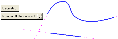
Geometric /
MorphThis is a toggle option that determines where the intermediate curve is created.
Geometric
The intermediate curve is created along a group of points where each point has the same distance to the 2 input geometries – the input wire(s) (or its extension) or to the point.
ExampleExampleThe mid curve is displayed in BLACK.
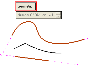
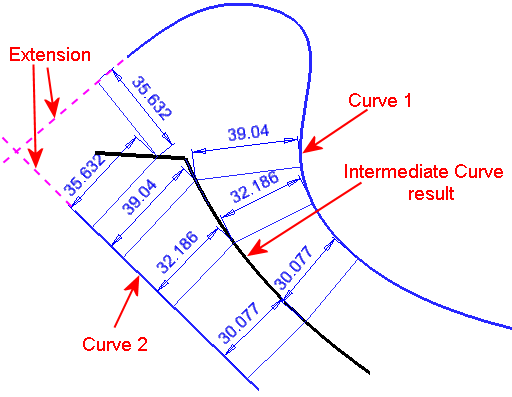
See the additional examples below.
See the note in the Number of Divisions parameter explanation below.Morph
The intermediate curve is created along the ½ V parameter of the "theoretical ISO parametric" ruled face created between the 2 input geometries.
ExampleExampleThe mid curve is displayed in BLACK.
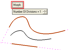
See the additional examples below.
Additional examples showing the difference between the Geometric and Morph options:
Between a circle and a pointBetween a circle and a point
The intermediate curve is displayed in BLACK.
Geometric
Morph
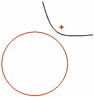
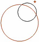
Between a wire (with 2 sharp lines) and a pointBetween a wire (with 2 sharp lines) and a point
The intermediate curve is displayed in BLACK.
Geometric
Morph
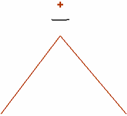
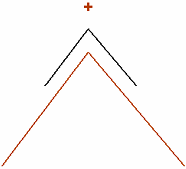
Number of Divisions
The number of curves to be created between the 2 input geometries.
ExampleExampleIn this example, Number of Divisions = 5.
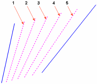
Note: If the Geometric toggle option is selected, the Number of Divisions is set to 1 and grayed out in the following cases: if the input curves are 3D or if the two 2D input curves do not lie on the same plane.
ExampleExample3D input curves
2D input curves on different planes


-
Pick the entities as required.
Pick the 2 input geometries (curves / lines / composite / sketches / edges / points) between which to create the intermediate curve(s)/point(s). The 2 input geometries can be:-
2D or 3D
-
Open or closed wire
-
Not smooth
-
1 wire and 1 point
-
2 points
The 2 input geometries cannot be 1 closed wire/curve and 1 open wire/curve.
If it is, an appropriate message is displayed.
Each input (wire) should not contain more than 1 loop (lump).
If it does, an appropriate message is displayed.
-
-
Define the parameters as appropriate.
-
Click OKOK or ApplyApply in the Feature Guide to complete the function. The result is single curve wire body.
When completed, the Intermediate Curve feature(s) will appear in the Feature Tree.

|

