|
|
Motion Editor > Delete Motions : Options and Results
![]()
![]()
Select the procedure (from the Process Manager) and do one of the following:
-
Press the
 button
from the toolbar.
button
from the toolbar. -
Choose NC Utilities > Motion Editor > Motion Editor from the menu bar.
-
Right-click on the procedure and select NC Guide Commands > Motion Editor from the popup menu.
Once in the Motion Editor, select Delete from the Motion Editor Guide.
OR (outside the Motion Editor):
Select NC Edit > Delete Motions > Delete Motions from the menu bar.
The Motion Editor Delete tool enables you to delete or trim one or many toolpath segments.
Note: In some cases it is more efficient to use motion editing on the procedure rather than editing it. In the example below, part of the toolpath is deleted.
|
Before trimming/deleting |
After trimming/deleting |
|
|
|
Required Step 1 
Pick the toolpath motions to be deleted. If necessary, use the Navigator to hide or show portions of the toolpath.
The following select options are displayed:
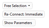
Gaps are closed immediately after deletion if Re-Connect: Immediate is selected.
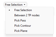
Use the top dropdown to filter the elements that can be selected, the options are; Free Selection (no restrictions); Between 2 TP nodes (path sections between two toolpath nodes); and Pass, Contour, or Plane which filters by that element.
Some selections accept additional settings: For more see Selection Options.
|
Setting |
Selection |
Description |
|
Offset Value |
Contour and Plane |
Set an offset from the selected entity |
|
Trim/Delete |
Contour and Plane |
Whether to trim or delete the picked segments |
|
In/Out |
Contour |
Define which side of the closed contour to pick the segments. |
Note: Click Show Parameters to open the Connection Settings dialog.
Example
In the example below, the Pick Contour option is used:
-
Using the Pick Contour option, pick the contour which is to be used to delete/trim the motions.
A prism of the extruded contour is displayed on the screen. By default, the prism is in the Z direction as shown in the picture below (the direction is represented by an arrow). To change the prism direction, use the directional arrow.
-
Click the Preview button
 (in the Feature Guide) to automatically preview the result of the delete operation.
Note: The motions within the area bounded by the contour are deleted.
-
If required, use the Offset Value parameter to set an offset from the trimming/deleting contour. A positive offset is always enlarging the contour. A negative offset is always decreasing the contour, regardless of the In/Out parameter.
-
If required, use the In / Out toggle parameter option to decide from which side of the contour to trim/delete the motions.
Note: To avoid cutting any essential motions, such as Air Motions (Feed, Max. Feed, Rapid) or Approach and Retract motions, use the Global Filter / Navigator to switch off the display of these motions.
-
The updated motions are displayed.
Note: By deleting these motions, gaps now appear in the toolpath (the gaps are signified by start and end gap points). If you attempt to exit the Motion Editor, a message is displayed informing you that gaps still exist and prompting you to Connect these gaps before you can exit the Motion Editor. You can also use the Optional Step 1, described below, to close the gaps of specific types of motions.
Connect gaps in the toolpath by creating motions along the contour. This optional step is only available if the Pick Contour selection option is used and the Trim toggle parameter is selected.
This optional step is best explained by using a different part to that used in explaining the Required Step 1 above.
In this case, in the Required Step 1 the highlighted contour has been picked and the direction is as shown below:
Note: The additional motions (created along the selected contour to connect the gaps in the toolpath) are linear, from Start Gap Points to corresponding End Gap Points. No gouge checking is done when these additional motions are created. Therefore, it is advisable to use Project Motions after these connect motions have been created.
|