|
|
Motion Editor > Selection Options
![]()
![]()
Access: To access the Motion Editor, select the procedure (from the Process Manager) and do one of the following:
-
Press the
 button from the toolbar.
 -
Choose NC Utilities > Motion Editor from the menu bar.
-
Select Motion Editor from the NC Guide.
-
Right-click on the procedure and select Motion Editor from the popup menu.
The Motion Editor uses various selection methods to pick toolpath segments for editing.
The selection methods used by the Connect tool of the Motion Editor are described in the Connect Help topic.
The Delete, Project, and Gouge Check tools of the Motion Editor all use similar selection methods and these are described below.
Note: When picking the toolpath motions to be edited, use the Global Filter / Navigator, if necessary, to hide or show portions of the toolpath.
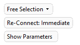
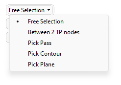
The following selection options are displayed in the Delete, Project, and Gouge Check tools:
 |
|
The Gouge Check tool has the following additional selection optionsadditional selection options:
|
Note: When running a Gouge Check, the results are displayed at the end of each check.
Free Selection
Pick specific toolpath segments to edit. Multiple segments can be picked By Box. To unpick your previous selection, either re-pick the segment or, in the case of multiple segments, press the Shift key and re-pick By Box.
Examples
-
Picking a single toolpath segment:
|
(in this case for Delete). |
The segment is deleted. |
|
|
|
A gap in the toolpath has now been created. This gap is marked by start and end gap points.
|
|
Start gap point. |
|
|
End gap point. |


-
Picking multiple segments using By Box:
Drag a box as indicated in the picture. Zoom in the area to select a point between motions; otherwise you select a specific motion.
|
|
|
This results in the following selection as all toolpath nodes included in the box are picked and all segments connected to these nodes are also picked:
Note: When running a Gouge Check, the results are displayed at the end of each check.
Between 2 TP Nodes
Pick two toolpath (TP) nodes. All toolpath nodes between the two picked nodes are selected for editing.
Note: Highlighting a segment will highlight the TP Node at the end of the segment. When the cursor moves to the next segment, the TP Node at the end of this next segment is highlighted. Therefore, when using the Between 2 TP Nodes option to pick a specific TP Node, pick the segment to which the node belongs - don't try to pick the actual TP Node as the cursor may move to the next segment and the TP Node at the end of this next segment will be highlighted. This is shown in the movie below:
|
Demo: Press the button below to view a short movie demonstrating the function: |
|
|

Examples
|
Pick the first node: |
Pick the second node: |
|
|
|
|
All nodes between the two picked nodes are selected: |
Perform the required editing operation; in this case Delete Motions. |
|
|
|
Note: When running a Gouge Check, the results are displayed at the end of each check.
Pick Pass
Pick a pass to assist in picking multiple segments. A pass or slice is a section of the toolpath at one z-distance from the surface of the workpiece.
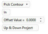
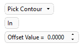
Pick Contour
Pick a contour to assist in picking multiple segments. The contour must be a closed 2D/3D contour, Sketch, PolyLine, or NC contour.
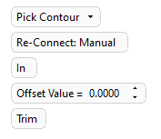
Each of the Motion Editor tools where this pick option appears, have similar parameters (see the parameter explanations below):
|
Delete parameters: |
Project parameters: |
Gouge Check parameters: |
|
|
|
|
Examples
-
Pick the closed contour which is to be used to perform the required Motion Editor operation on the motions.
A prism of the extruded contour is displayed on the screen. By default, the prism is in the Z direction, as shown in the picture below (the direction is represented by an arrow). To change the prism direction, use the directional arrow.
|
In / Out |
A toggle option to define which side of the closed contour to pick the segments. Delete examples:
|
||||
|
Offset Value |
Set an offset from the picked entity (in this case a contour). Delete examples:
|
||||
|
Trim / Delete |
A toggle option in Delete only. Decide whether to trim or delete the picked segments. |
Note: When running a Gouge Check, the results are displayed at the end of each check.
Pick Plane
Pick a plane and the system selects all toolpaths segments that are cut by this plane. A plane or planar face can be picked.
Each of the Motion Editor tools where this pick option appears, have similar parameters:
|
Delete parameters: |
Project parameters: |
Gouge Check parameters: |
|
|
|
|
These parameters have been explained under Pick Contour.
Examples
-
Pick the plane which is to be used to perform the required Motion Editor operation on the motions.
A toggle arrow is displayed to enable you to pick the side on which to perform the operation.
Pick the arrow to flip the direction; this picks the toolpath segment on the other side of the plane. Picking another plane or planar face, un-picks the previous selection.
|
|
|
Note: When running a Gouge Check, the results are displayed at the end of each check. The Gouge Check tool has the following additional selection optionsadditional selection options:
Manually Edited
This selection option only appears in the Gouge Check tool and automatically selects all motions that were manually edited using the Motion Editor.
When running a Gouge Check, the results are displayed at the end of each check.
All Against Parts
This selection option only appears in the Gouge Check tool and performs a gouge check against all the surfaces of all the Part procedures that are above the current procedure in the Process Manager.
The following parameters are displayed:
|
Number of Surfaces |
System generated parameter specifying the number of part procedure surfaces. |
|
Surface Offset |
An offset can be set for the surfaces. |
To start a gouge check, set the Surface Offset value and click OK or Apply.
When running a Gouge Check, the results are displayed at the end of each check.
When All Against Parts is selected, the Gouge Check optional steps are grayed out and cannot be used.
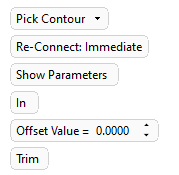
Re-Connect: Immediate
This option operates immediately after each trim or delete according to the connections defined in the connection settings.
The Show Parameters button opens the Connection Setting dialog.
|