|
|
Simulation Motions List 
![]()
![]()
Access: Invoke the Machine or Material Removal Simulator and select Simulation Motions List from the Simulator Guide.
Shows all the motion blocks of the current procedure and the progress bar for all the simulated procedures.
The Motions List tool shows the procedures list on top and the motion coordinates below. The displayed dialog is similar to the Simulation Report dialog. The principal differences are that the Motions List shows all the blocks and not just the problematic ones. There are no problem details in the problematic block; those are only marked by a red exclamation mark.
The functionality in both the dialogs (Motions List and Simulation Report) is the same. Selecting a procedure will show its relevant motion and show the relevant cutter in position of the first block of the selected procedure. Selecting any block from the list will position the tool in the appropriate position. Clicking the up/down keyboard arrows advances the tool accordingly.
If the selected block is a problematic one, the tool and other relevant part elements (which are hidden at this point) will turn red.
The Report dialog is displayed and differs slightly in the Machine Simulator and the Material Removal Simulator; the Machine Simulation Report dialog has two display modes: By Block and By Coordinates.
The general functionality of the Motions List dialog is the same in both the Machine Simulator and the Material Removal Simulator.
Machine Simulator Motions List dialog
Material Removal Simulator Motions List dialog
See:
Simulation Motions List Dialog Parameters
Machine Simulator Motions List dialog
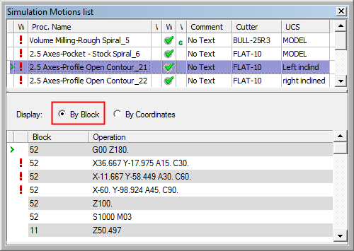
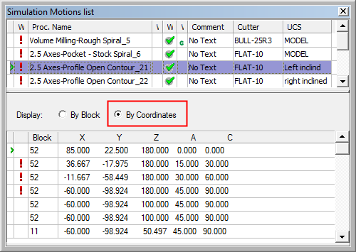
The Simulation Motions List dialog appearing in the Machine Simulator is shown below. The By Block and By Coordinates options control the type of information that is displayed (both display modes are synchronized; switching between the modes shows the same position):
|
|
|
See:
Simulation Motions List Dialog Parameters
|
By Block |
This option displays the Operation column showing the same output which is output to the program file. This display mode is gray and white striped. This is to enhance the visualization of the different motions. The post processor may output some non-motion commands (such as comments, M-codes, etc.) in the same block with a motion command. In some cases it may output only non-motion commands. This is the reason why the strips are sometimes wider than a single row. |
|
By Coordinates |
This option displays shows the block number and the position coordinates of all machine axes. Note that the displayed coordinates are measured from the Reference UCS to the Tool Tip. These are also displayed as the current position display, in the Machine Simulation Control dialog. |
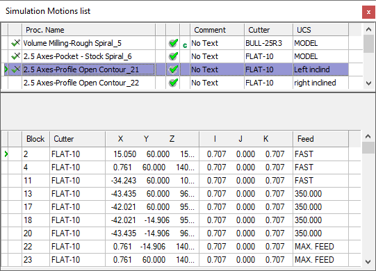
Material Removal Simulator Motions List dialog
The Simulation Motions List dialog appearing in the Material Removal Simulator is shown below.
|
|
Note that the feed rate of each motion is displayed in the Motions List table, in the Feed column. This enables you to see where and how the feed rate changes.
See: |
Simulation Motions List Icons
As in the Simulation Report, in the top area, a list of all the procedures that were selected to be simulated is shown. For each procedure there is information about its name, comment, cutter, UCS and the procedure flag, as appears in the NC Process Manager.
The symbol on the left of each procedure indicates the following simulation state:
|
|
Fully simulated: no problem(s) found. |
|
|
Partially simulated: no problem(s) found. |
|
|
Fully simulated: some problem(s) found. |
|
|
Partially simulated: some problem(s) found. |
|
No Symbol: not simulated yet. |
|