|
|
Simulation Control 
![]()
![]()
Access: Invoke the Machine or Material Removal Simulator and select Simulation Control from the Simulator Guide.
Control the cutter position and the stock removal.
The Simulation Control dialog is displayed and differs slightly in the Machine Simulator and the Material Removal Simulator:
|
Machine Simulation Control dialog: |
Material Removal Simulation Control dialog: |
|
|
|
|
See: |
Usage Example
Example of the Simulation Control dialog in use.
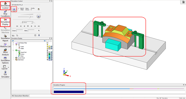
In the Simulation Control dialog, when the ![]() button is pressed to activate the simulation, the following occurs:
button is pressed to activate the simulation, the following occurs:
-
The Fast Forward (FF) button
 changes to Pause
  . Clicking on it will pause the simulation.
 -
The Progress bar advances as the simulation continues.
-
Neither tool movements nor material removal is seen on screen.
-
Tool(s) and stock disappear.
-
The Target part, Fixture and Other geometry elements are shown instead of the stock.
-
Other 'free' geometry display is left intact.
While the simulation runs, the simulator engine computes the material removal and checks for any possible gouges or collisions.
Simulation Control Dialog Parameters
The dialog controls are detailed below; some of these controls are very similar to those in the Navigator.
Note: Tool parameters appear in both the Machine Simulator and the Material Removal Simulator unless specified to the contrary.
|
<Procedure_Name># |
This is the name of the procedure which is currently simulated. It will be changed automatically as the procedure changes along the simulation process. In addition, the number of this procedure out of the total number of procedures to be simulated, is also displayed. |
||||||||||||||
|
|
Run: Simulate Fast Forward to end. When the Fast Forward (FF) button
The most common thing you would want from your simulator, is to be informed as fast and as simply as possible if there are any problems. The FF simulation mode serves just that. |
||||||||||||||
|
Ignore Stops |
Select the checkbox to ignore all the stop conditions and simulate until the end. The default setting is unchecked. |
||||||||||||||
|
Done |
The percentage of simulation done. It changes dynamically. |
||||||||||||||
|
Errors |
Shows the number of errors found up to the current simulation point. The image above shows 1 because the simulator stopped at the first error - see Stop Conditions. |
||||||||||||||
|
|
Report indication and button. This displays an immediate indication on the current state of the simulation:
In addition, this button is also used to open the Simulation Report dialog. |
||||||||||||||
|
|
Movie: Simulate to end. The movie shows the cutting tool moving in a constant smooth motion along the toolpath with, if relevant, the simultaneous removal of stock. When the Movie button is pressed to activate the movie mode simulation, the following occurs:
When the movie simulation stops (for any reason):
|
||||||||||||||
|
Step Size |
A dropdown list of step types by which to display the motions. This dropdown list is only available in the Material Removal Simulator. In the Machine Simulator, the Step size option is set to Procedure and the dropdown list is disabled. In the Material Removal Simulator the displayed motions are dynamically changed according to the type of Step selected. For example, if the selected step is By Layer, the motions displayed in the Simulation Display dialog, only show the motions of the current layer.
The following options are available in the Step dropdown list:
The inclusion of a Step type, in the Step dropdown list, is dependent upon its existence in the procedure. For example; if a procedure does not include layered motions, the By Layer option will not appear in the Step dropdown list. In the Machine Simulator, the Step size option is set to Procedure and the dropdown list is disabled. In addition to affecting the motion display, the Step options define the step size for the Forward
|
||||||||||||||
|
Z Layer |
This parameter only appears in the Material Removal Simulator. The Z layer of the cutter motion block currently displayed. This displays the current Z layer or enter a value to jump to a specific Z layer. |
||||||||||||||
|
Block |
Number of the cutter motion block currently displayed. This displays the current motion block or enter a value to jump to a specific motion block. See the |
||||||||||||||
|
|
Icon to show the current segment of the selected Step; linear, circular or spline. |
||||||||||||||
|
|
Pick and position the tool on a specific motion block in the display. |
||||||||||||||
|
|
Update the simulation to the current tool position. This is useful, for example when, at the end of the simulation process, you wish to investigate reported collisions that occurred during the simulation. At the end of the simulation, the stock is shown in its final state. However, when investigating a collision (for example by selecting a specific block from the Simulation Report), you require the stock state and tool position to be synchronized. This option updates the state of the stock to the current tool position. |
||||||||||||||
|
|
Go to (move the tool) to the current simulated position. This button moves the tool to the last (synchronized) simulation point. This mark appears each time the tool is moved from the synchronized position, either manually or by picking any block from the Motions List or Simulation Report dialogs. When this button is pressed, the tool is moved and the Update Simulation and Go To buttons, as well as the Sync. mark, are grayed out. |
||||||||||||||
|
|
Sync. When the Sync. mark is displayed, this indicates that the tool is not positioned at the last simulated point. This mark appears each time the tool is moved from the synchronized position, either manually or by picking any block from the Motions List or Simulation Report dialogs. |
||||||||||||||
|
|
Reset the Simulator and restore the initial stock. |
||||||||||||||
|
|
Exit the Simulator. |
||||||||||||||
|
<Axis Values> |
This area only appears in the Machine Simulator and displays the values of all the machine axes.
|
||||||||||||||
|
|
This button only appears in the Machine Simulator and displays the Axes Control dialogAxes Control dialog which enables you to manually manipulate the machine axes. This button is only available when the simulator is idle. The Axes Control dialog is displayed showing sliders for all the axes appearing in the Simulation Control dialog. When an axis is changed, this is reflected in the simulation window.
At the top of each axis a text box enables you to enter an axis value. The value shown in the text box is based on the active home value. These numbers are updated when moving the sliders. The axis limits of each axis are displayed at each end of the sliders. If an axis value entered in a text box is outside the axis limits, it is automatically modified to the nearest limit value. To return to the Simulation Control dialog, either press the Open Simulation Control button |
|