|
|
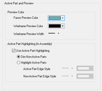
Modeling Preferences > Colors > Active Part and Preview

Access: Invoke this function from one of the following locations:
-
Select the Preferences button
 from the Quick Access Toolbar, or
 -
Select Tools > Main Tools > Preferences from the menu bar.
Navigate to Modeling > Colors > Active Part and Preview.
Set the default Preview colors and define the highlighting of active parts in the Assembly environment.
The Active Part and Preview dialog is displayed.
Interaction
Set the default preview colors for face and wireframe entities. Also, set the default preview pen width for wireframe entities.
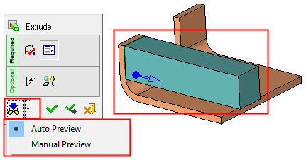
Example:Example:
In the example below, the Auto Preview option is enabled and you can immediately see the results of an operation (in this example, an Add Extrude operation) before executing the function. Note that the preview is displayed in the defined default color.
Define the highlighting of active parts in the Assembly environment. This is used to easily differentiate between active and non-active parts in an assembly. In the Assembly Tree, active parts are automatically highlighted in bold.
When this checkbox is marked  , you can either display non-active parts in a dimmed version of their original color on screen or highlight the active and non-active part based on edge display.
Example:Example:
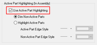
The following options are available when using active part highlighting:
|
Dim Non-Active Parts |
Dim the color of non-active parts. |
|
Highlight Active Parts |
Define the pen width and color for active and non-active part edges. |
When this checkbox is OFF  , all options in this section are grayed out. In this case, no color change occurs when activating parts and you need to use the Assembly Tree to determine which components are active.
Press the appropriate approval option.
|