|
|
Create Stock  : Box
: Box

Access: Open this function from one of the following locations:
Select the toolpath for which the stock will be created, and then create the stock in one of the following ways:
-
Select NC Process > Process > Stock from the menu bar.
-
Select
in the NC Guide Toolbar.
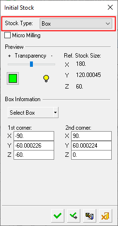
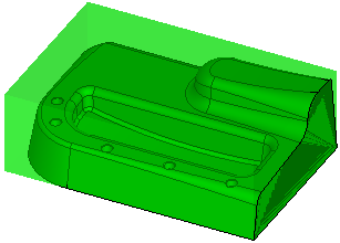
Define a stock by defining a box around the part. The box is formed by indicating minimum and maximum points.
By default, the stock box covers the whole part. The stock size and the XYZ coordinates of the two furthest diagonal points of the stock box are detailed in the Initial Stock dialog (see below).
To redefine the stock box, you can either pick two points or define the diagonal of the box. See the example of stock creation by box.
Note: A GREEN X is displayed when you are picking points.
The following dialog is used for stock creation by box.
|
|
Pick the box or pick two corners to defined the stock. See the dialog Parameter definitions below for more information. Procedures will update the stock immediately after their calculation or only when needed, depending on the relevant setting in the Preferences > NC > General Preferences.
|
Parameters
|
Micro Milling |
When this checkbox is marked
When calculating stock, the tolerance is considered as Micro Milling in either of the following circumstances;
|
||||||
|
Transparency |
Control the hide/show state, transparency, and color of the stock. |
||||||
|
|
|||||||
|
Ref. Stock Size |
The reference stock size based on the entities you have selected. This area shows the size of the stock. The values are for reference only and cannot be changed in this dialog. The Z distance is the difference between the Max. Z and Min. Z values (in the Selected Geometry section of this dialog). |
||||||
|
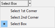
Select Box |
Select the method by which to define the stock box. Initially, by default, the box covers the whole part while displaying the XYZ coordinates of the two furthest diagonal points of the stock box. The following options are available from the dropdown list.
See the example of stock creation by box. |
||||||
|
1st corner, 2nd corner |
Based on the entities you have selected, this area shows the XYZ coordinates of the diagonal of the box. These values can be changed manually. |


When finished, press one of the approval options.
|
|
OK: Accept the changes, perform the operation, and close the current dialog/task. The stock/part is calculated. |
|
|
Apply: Accept the changes, perform the operation, and keep the current dialog/task open. The stock/part is calculated. |
|
|
Save: Save the settings. Suspend and calculate later. |
|
|
Cancel: Cancel all changes and close the dialog/task without saving the settings. |
|