Gate Design  : Options and Results


Access: Open this function from one of the following locations:
-
Select Mold Design > Runner > Gate Design from the menu bar.
-
Select Runner Design > Gate Design from the Mold Design Guide Toolbar.
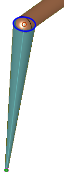
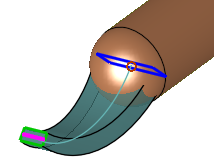
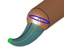
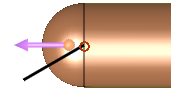
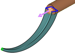
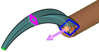
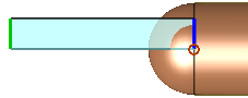
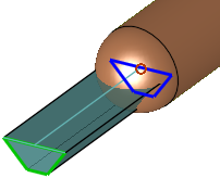
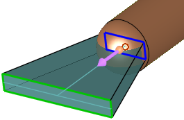
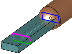
Design the melt entrance gate.
Required Step 1 
Select the gate options and set the parameters. When the function is invokedinvoked, the runner part of the assembly is automatically activated or created (if a runner part cannot be found). If a runner part is created, the Direct Gate type is selected by default.
The following parameters are displayed, depending on the gate type selected:
|
|
Gate type options Edge Gate Fan Gate Tunnel Gate Curved Tunnel Gate Pinpoint Gate Direct Gate |
|
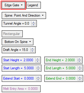
Edge Gate: |
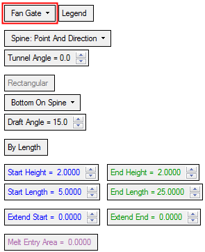
Fan Gate: |
Pinpoint Gate |
Direct Gate |
|
|
|
 |
 |
|
Tunnel Gate, Rectangular: |
Tunnel Gate, Circular: |
||
|
|
|
||
|
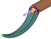
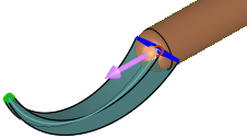
Curved Tunnel Gate, Rectangular: |
Curved Tunnel Gate, Circular: |
||
|
|
|
Parameters by Gate TypeParameters by Gate Type
|
|
|
|
|
|
|
|
Parameters
|
Edge Gate |
This is a dropdown list containing the following gate types:
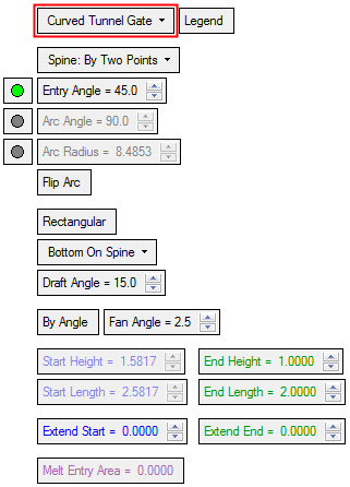
Curved Tunnel GateCurved Tunnel Gate
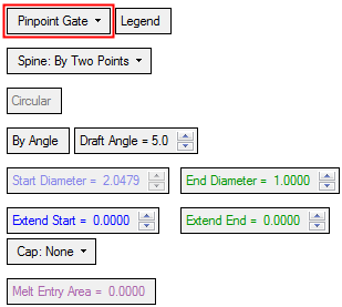
Pinpoint Gate
|
||||||||||||||||||||||||
|
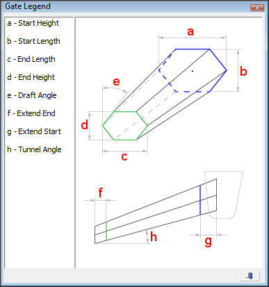
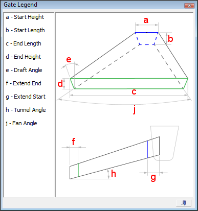
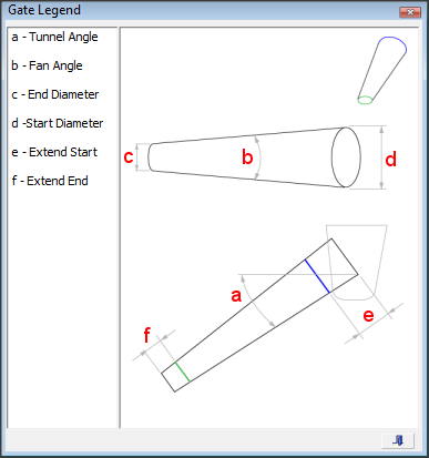
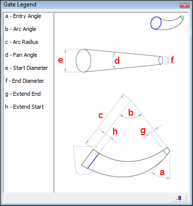
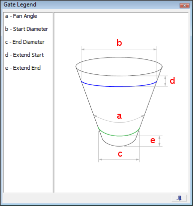
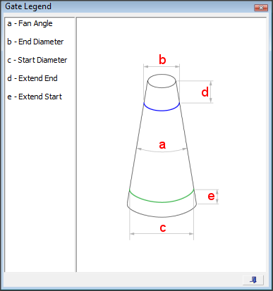
Legend |
Displays a dialog explaining the parameters of the current gate option selected.
Curved Tunnel GateCurved Tunnel Gate
|
||||||||||||||||||||||||
|
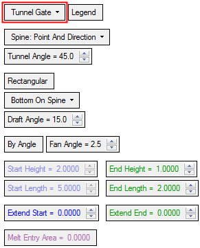
Spine: Point & Direction |
This is a dropdown list of the following methods of defining the spine:
|
||||||||||||||||||||||||
|
Tunnel Angle |
Set the angle of the tunnel from the spine direction. This option is displayed if the Edge, Fan, or Tunnel Gate is selected together with the Spine: Point & Direction option above.
|
||||||||||||||||||||||||
|
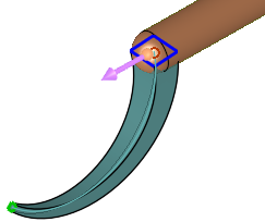
Entry Angle |
These parameters are displayed for the Curved Tunnel Gate.
When the Spine: By Two Points option is used, only one of the above parameters can be defined (the parameter with the adjacent green button); the other two parameters are system-calculated as a result of the set parameter.
|
||||||||||||||||||||||||
|
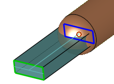
Rectangular |
This is a toggle option that determines whether the gate is Circular / Rectangular.
|
||||||||||||||||||||||||
|
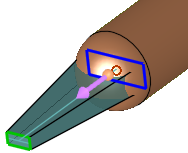
Bottom on Spine |
This is a dropdown option that determines the position of the gate relative to the spine:
|
||||||||||||||||||||||||
|
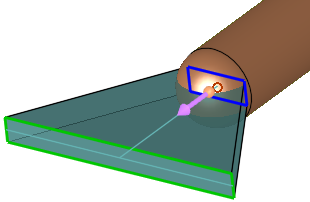
Draft Angle |
Define a draft angle for the gate. The shape of the draft angle is determined by the position of the gate relative to the spine:
For the Manual Selection option, the Draft Angle behaves as follows:
|
||||||||||||||||||||||||
|
By Length / By Diameter |
This is a toggle option By Length / By Angle or By Diameter / By Angle that determines the shape of the selected gate option.
Notes:
|
||||||||||||||||||||||||
|
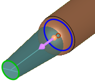
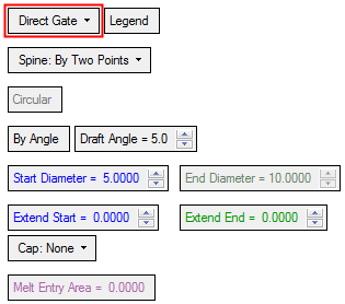
Start/End Diameter |
Define the gate diameter at the start (close to the runner) and end (close to the part) of the section.
This parameter is displayed if the Circular option is selected. |
||||||||||||||||||||||||
|
Start/End Height |
Define the gate height at the start (close to the runner) and end (close to the part) of the section.
This parameter is displayed if the Rectangular option is selected. |
||||||||||||||||||||||||
|
Start/End Length |
Define the gate length at the start (close to the runner) and end (close to the part) of the section.
This parameter is displayed if the Rectangular option is selected. |
||||||||||||||||||||||||
|
Extend Start/End |
Define the gate extension at the start (close to the runner) and end (close to the part) of the section.
|
||||||||||||||||||||||||
|
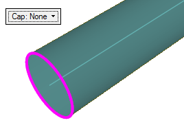
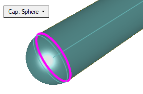
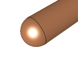
Cap |
This is a toggle option Cap: None / Cap: Sphere that determines the shape of the end of the gate.
This parameter is displayed when the Pinpoint Gate or Direct Gate options are selected. |
||||||||||||||||||||||||
|
Melt Entry Area |
Displays the area of the entry hole. This parameter is informative only. |
||||||||||||||||||||||||
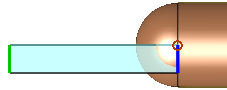
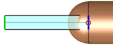
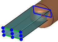

Optional Step 1 
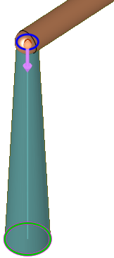
Offset the start and end points. This step is not available if the Spine: Selected Curve option was selected above.
The following parameters are displayed.
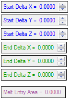
The Start Delta parameters are only available if a start point was created, and the End Delta parameters are only available if an end point was created.
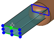
If the Spine: By Two Points option was selected, any change adds a delta to the relevant point.
If the Spine: Point & Direction option was selected, a change on that point will be processed first. Then the 2nd point will be defined and then a delta on it. For example:
If you selected a point on the runner (start) and entered a delta on the end point, it will change the position of the end point.
If you selected a point on the runner (start) and entered a delta on the start point, it will change the position of the start point and then recreate the line.
If you selected a point on the runner (start) and entered a delta on the start point and on the end point, it will change the position of the start point and then recreate the line, and then add the delta to the end point.
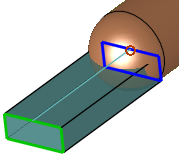
The Melt Entry Area displays the area of the entry hole. This parameter is informative only.
Press OK ![]() or Apply
or Apply ![]() in the Feature Guide to complete the function.
in the Feature Guide to complete the function.
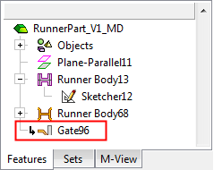
When completed, the Gate feature will appear in the Feature Tree.