|
|
Setting a Direction: By UCS and Angles

Access:
Click the base of the Directional
Arrow to display the toolbar of direction options. Select the
By Angle option ![]() .
.
Set a direction by angle using the By Angle > By UCS & Angles option.
|
Demo: Press the button below to view
a short movie demonstrating the function:
|
Practice: Press the button below to open Cimatron with a practice ELT file similar to that used to create the movie (if the relevant feature already exists in the ELT file, you can either edit it or delete it and create a new feature). |
|
|
|

In the example below, the Add Extrude function is to be used to extrude the circle.
|
Extrude the circle. |
By default, the extrude direction is normal to the plane/face of the entity. |
To select another direction, select the arrow base. |
A toolbar of direction options is displayed. For this example, select the By Angle option |
|
|
|
|
|
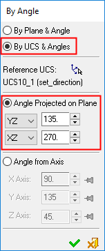
The By Angle dialog is displayed; select the By UCS & Angles option.
|
By UCS & Angles: |
By UCS & Angles: |
|||||
|
|
|
This dialog enables you to define the following:
|

To set the direction vector, select a reference UCS and set the angles.
Angle Projected on Plane
This option indicates the angle between the projection of the arrow direction on the selected plane and the axis (the X axis for the XY and XZ planes, the Y axis for the YZ plane). Using this option, it is possible to define the angle for the Top / Front / Right view.
 |
To change the projected angle:
|

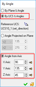
Angle from Axis
Enter the required angles values for each axis (based on the reference UCS).
 |
To change the projected angle:
Fix/Float buttons are associated with each angle. These can be set automatically or manually. Automatic Fix: The first changed axis is the dominant axis. This angle value does not change when the second or third axis angles are changed. Once you change the value of the second axis, the first changed axis automatically becomes Fixed. Manual Fix: Press the appropriate Float |
 button to toggle it to
  . This angle value does not change, until you either toggle the button back to Float, or you set another axis as Fixed. Only one axis can be defined as Fixed; setting a subsequent axis to Fixed, automatically toggles another Fixed axis to Float.
|