|
|
Skeleton Curve  : Options and Results


Access: Open this function from the following location:
-
Select Wireframe > Derived Curves > Skeleton Curve from the menu bar.
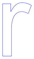
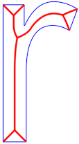
Find the skeleton (middle curve) of selected 2D contours or planar faces. For planar faces, the system creates a skeleton curve based on the boundary edges of the selected face.
Required Step 1 
-
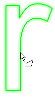
Pick closed contour(s) or planar face(s).
-
Click <Exit><Exit> to proceed to the next step.
Required Step 2 
-
Set the parameter values.
-
If closed contours were selected in step 1, the skeleton (middle curve) of the selected 2D contours is displayed.
-
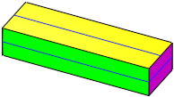
If planar faces were selected in step 1, the system creates a skeleton curve based on the boundary edges of the selected face.
-
If adjacent faces with the same plane are selected, a single skeleton curve is created.
-
If non-adjacent faces or faces which do not share the same plane are selected, different skeleton curves will be created on each selected face.
Parameters
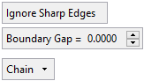
Ignore Sharp Edges /
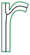
Include Sharp EdgesThis toggle option allows you to ignore or include sharp edges when creating the middle curve. A sharp edge is defined as ≤ 160°.
Ignore Sharp Edges
Do not extend the middle curve to sharp edges. See the examples below. This is the default option.
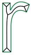
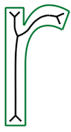
Include Sharp Edges
Extend the middle curve to sharp edges. See the examples below.
Ignore Sharp Edges
Include Sharp Edges
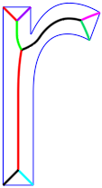
Boundary Gap
Set a gap between the middle curve and the boundary of the selected contour.
Default = 0 mm
Min: 0 mm
Max: 1000 mm depending on the bounding boxIgnore Sharp Edges
Include Sharp Edges
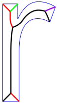
Boundary
Gap = 0Boundary
Gap = 0.7Boundary
Gap = 0Boundary Gap
= 0.7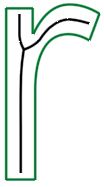
Chain
This is a dropdown list of the following options to define how the skeleton curve is to be created. See the example images below.
Exploded Segments
Each curve segment that reaches a split vertex is created as a separate segment.
Chain
For each curve segment, the system creates the longest possible continuous segments. This is the default option.
Single Wire
All curve segments are combined into a single wire.
Exploded Segments
Chain
Single Wire
-
-
The skeleton (mid) curve(s) of the selected geometry are displayed with the following parameters.
If faces which do not share the same plane are selected, different skeleton curves will be created on each selected face, as shown in the image below.
-
Click OKOK
 or ApplyApply
 in the Feature Guide to complete the function.
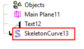
When completed, the Skeleton Curve feature will appear in the Feature Tree.

|