Cutters & Holders Parameters  : Machining Parameters

Access: Open this function from one of the following locations:
The Cutters and Holders dialog (or the minimized version - the Select Only Mode):
-
When not editing or creating a procedure, select NC-Process > Cutters > Cutters from the menu bar or select Cutters
in the NC Guide Toolbar. -
While editing or creating a procedure, use one of the following methods (in both methods, the Select Only Mode is displayed):
-
In the Advanced Mode, click on the cutter name in the Procedure Parameter Table.
-
In the Wizard Mode, select the cutter button.
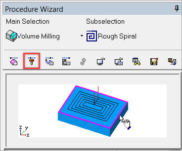
-
-
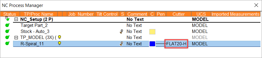
In the Process Manager, click on the cutter name in the procedure row (in this case, the Select Only Mode is displayed).
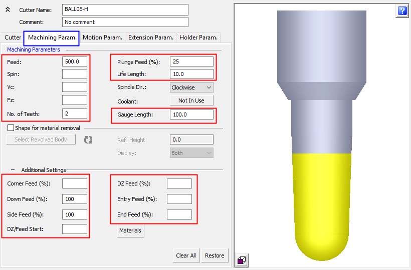
This topic discusses how to set default Machining Parameters for a specific cutter.
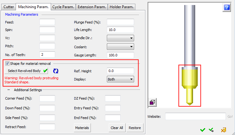
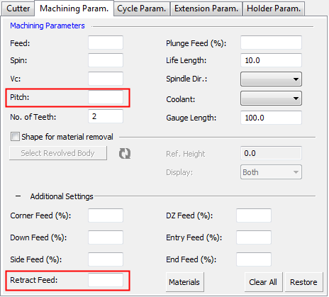
In the image below, parameter fields in the red highlighted areas will accept expressions, such as 7/8, 5/25.4. Relations to other parameters (such as tldi/2) cannot be defined.
To display additional parameters, click the relevant tab in the dialog image below.
In this topicSee also
|
|
||||||||||||||||||
Shape for material removal
A revolved body shaped can be attached to any cutter and this shaped figure data is used for:
Material removal and updating the stock in Remaining Stock calculations.
Simulation collision check calculations.
Cutter display representation in the Navigator.
The standard figure data is considered during execution.
The process to attach the revolved body shape to a cutter and the Ref. Height parameter, are the same as for Special Shaped Cutters.
When the Shape for Material Removal checkbox is checked, the relevant parameters are enabled.
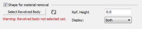
Messages are displayed to describe the state of the shaped figure, such as the message below that states that the shaped figure is not contained within the standard cutter volume.
|
Ref. Height |
This is used to shift the shaped figure up and down along the cutter axis. |
||||||||||||
|
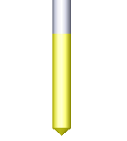
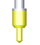
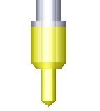
Display |
This is a dropdown list that defines the display of the cutter in the Cutter Preview Pane of the dialog, and also in the graphics pane while performing Navigator operations.
|
Notes:
-
The section data (the defined revolved body shape and other parameter settings in this section) are maintained if the Shape for Material Removal checkbox is unchecked. If the checkbox is checked again, the section data is restored.
-
The attached revolved body is used for material removal in Remaining Stock calculations.
-
A change in the attached revolved body shape, its orientation, its Ref. Height, or its "Cut" segment height will cause the calculated Remaining Stock to become irrelevant.
-
When a change in the standard shape has no impact on the shape that was used for Remaining Stock calculations and the procedure motions remain (the procedure did not become suspended), the calculated Remaining Stock is still relevant.
-
-
The attached revolved body is used for Simulation.
-
The attached revolved body is used for the cutter representation in the Navigator.
-
The calculation of the milling motions is done while using the Standard shape of the cutter.
-
You can manipulate the display, hide/show, and ZPR in order to clearly investigate the standard shape and the attached revolved body together and each one separately.
-
You will receive notifications about the relations between the standard shape and the attached revolved body shape.
-
You can export and import the Shapes attached to the cutters to and from CSV and Excel files.
-
The information that a revolved body shape is attached to the cutter for usage is passed to the Post-Processor and to the NC Report.
-
Drilling parameters
Some of the parameters in this tab are only displayed if Drilling is selected as the Technology in the Cutter tab. These parameters are highlighted in red in the example below.
Using these parameters within a procedure
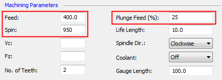
In this example, the following Machine Parameters have been defined for a cutter:
|
In the Cutters and Holders dialog: |
Within the NC procedure, the corresponding parameters have already been defined with different values. |
|
|
|
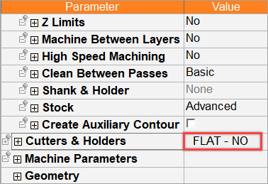
Using the cutter-specific machine parameters
-
Right-click on the Parameter section of the NC procedure to display the popup menu and select the appropriate option.
-
For example, select the option Set machine params only. The relevant Machine Parameters in the NC procedure are set according to the values in the Machine Parameter tab of the Cutters & Holders dialog. They are displayed below, on the left, as changed values.
New values
Original values