|
|
Validate Holes  : Pane

Access: Open this function from the following location:
-
Select Mold Design > Cooling > Validate Holes from the menu bar.
If analysis data already exists, the Validate Holes Pane is automatically displayed, showing the results of the analysis.
If analysis data does not exist, the Validate Holes function is opened. Set the parameters and click Start Analysis; the Validate Holes Pane is displayed, showing the results of the analysis.
The Hole Validation Pane displays the results of the Validate Holes analysis.
Mold makers commonly receive mold design jobs from sub-contractors or receive maintenance jobs on molds they did not design. In these cases, some of the holes may not follow the shop floor standards and require mold makers to change them to fit their drilling standards. The Validate Holes function enables the mold maker to quickly and easily analyse the holes used in the design and to ensure all of them adhere to the standards.
If analysis data already exists from the Validate Holes function, the Validate Holes Pane is automatically displayed, showing the results of the analysis.
If analysis data does not exist, the Validate Holes function is opened. Set the parameters and click Start Analysis; the Validate Holes Pane is displayed, showing the results of the analysis.
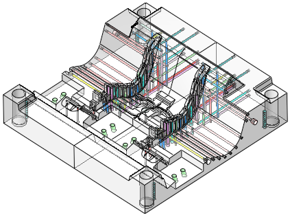
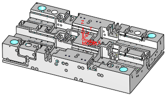
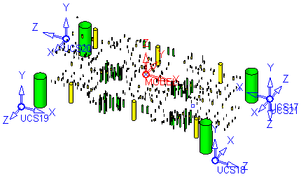
In the Validate Holes Pane, the objects/faces selected for analysis are displayed in transparent gray, with the groups of holes colored as defined in the Validate Holes dialog (shown on the right). The image below shows holes sorted into groups of recognized hole types.
|
|
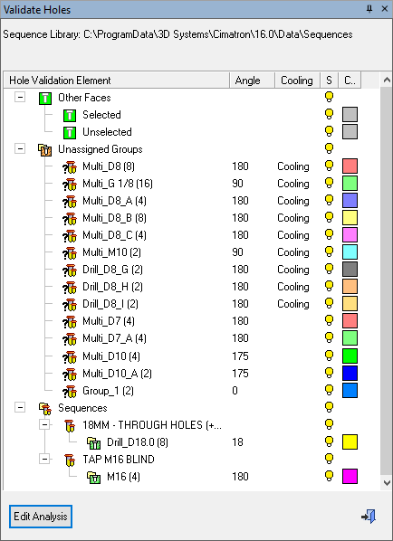
Example of the Validate Holes dialog |
See:
Dialog Structure
The dialog displays the analysis results in a tree structure. It displays the following information:
-
The Sequence Library folder name.
-
Information about the selected holes and the hole groups
-
Information about the sequences
-
Options for choosing the display color of holes and surfaces
-
Hide / Show of hole groups
-
Color changing of hole groups
-
Popup menus that enables a set of relevant services (e.g. Auto Fit Sequence, Delete).
-
Update status
-
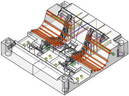
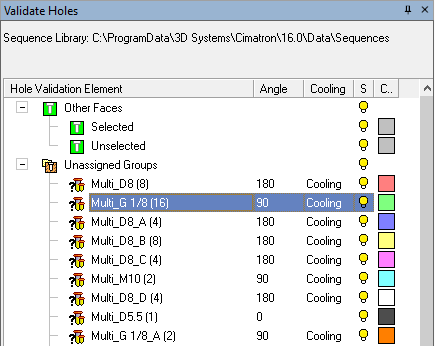
Bidirectional highlight with the entities on the graphic area; as shown in the images below.
When clicking on the name of a particular group in the Validate Holes dialog, the holes of that group are highlighted in the model. Conversely, when clicking on a hole in the model, all the holes in the same group are highlighted, as is the group name in the Validate Holes dialog.
|
|
|
The dialog displays the following columns:
|
Hole Validation Element |
Displays the various elements found after the analysis. The elements are assigned to Other Faces , Unassigned Groups and Sequences. Hole groups can be found under the unassigned groups branch as well as the various sequence branches. Branch Descriptions:Branch Descriptions:
|
|||||||||||||||||||
|
Angle |
Displays the angle of the hole from the Z direction (the angle that is taken into account in the NC Drilling parameter Max. Inclination Angle). This is the maximum gap allowed
between the selected geometries, when joining them into a single geometry.
If the gap between the selected geometries is greater than the Max. Gap value, they are treated as separate
geometries.
|
|||||||||||||||||||
|
Cooling |
Displays the word Cooling next to groups that are defined as cooling. |
|||||||||||||||||||
|
S |
Hide / Show specific items. The appropriate bulb status is displayed.
|
|||||||||||||||||||
|
C |
Change the color of an item . The appropriate color icon is displayed.
|


Dialog Buttons
|
Edit Analysis |
Edit Analysis: Open the Validate Holes function to edit the analysis parameters. Click the Start Analysis button in the function to re-run the analysis. The results of the new analysis are displayed in the Validate Holes Pane. |
|
|
Exit: Exit the operation and close the dialog/task. |
Dialog Operations
Double clicking an unassigned group will open the sequence definition.
Double clicking a sequence will open its sequence definition for editing.
Double clicking a group will display the view of the group.
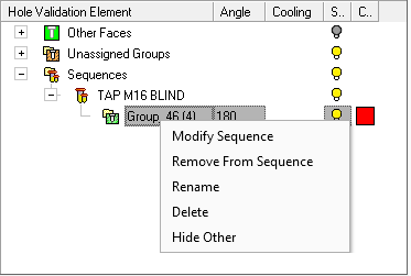
Popup Menu
Right-click on one of the following tree items and the relevant popup menu is displayed.
Multiple Selection
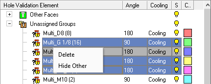
The multiple selection popup options are described below, as they also appear in the menus when right-clicking a single group.
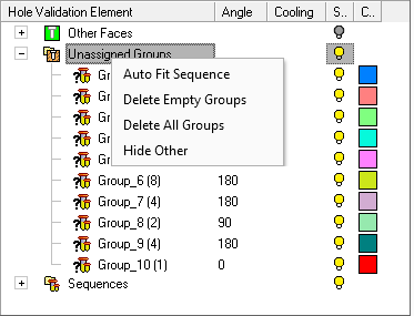
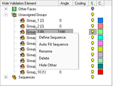
Unassigned Groups
|
Unassigned Groups (branch) |
Unassigned Groups (Group) |
|
|
|
|
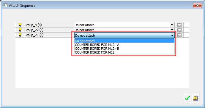
Search for a sequence and attach it to the selected group.
If the search for predefined
matching hole sequences results in multiple solutions (more than one fit)
for one or more groups, the Attach
Sequence dialog is displayed enabling you to choose which group
to attach to which sequence.
|
|
|
Define/edit a Hole Sequence.
A Hole Sequence is a set of faces describing a hole.
|
|
|
Delete |
Delete the selected item.
|
|
Delete All Groups |
Delete all the groups under the selected item.
|
|
Delete Empty Sequences/Groups |
Delete all the groups with no holes and/or all the sequences with no
groups.
|
|
Hide everything except for the selected/highlighted geometry. |
|
|
Rename |
Rename the selected item.
|
Sequences
|
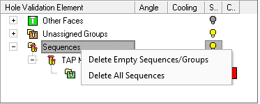
Sequences (branch) |
|
|
|
|
|
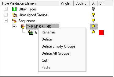
Sequence (twig - under the Sequences branch) |
Sequence Group |
|
|
|
|
Cut / Paste |
Cut / Paste a sequence.
|
|
Define/edit a Hole Sequence.
|
|
|
Delete |
Delete the selected item.
|
|
Delete All Groups |
Delete all the groups under the selected item.
|
|
Delete All Sequences |
Delete all the sequences. All the groups contained in the deleted sequences
are transferred to Unassigned Groups.
|
|
Delete Empty Sequences/Groups |
Delete all the groups with no holes and/or all the sequences with no
groups.
|
|
Hide everything except for the selected/highlighted geometry. |
|
|
Remove From Sequence |
Remove the group from the sequence.
|
|
Rename |
Rename the selected item.
|
|