|
|
Volume Text  : Options and Results


Access: Open this function from one of the following locations:
-
Select Solid > Creation > Volume Text from the menu bar.
-
Select Mesh > General Tools > Volume Text from the menu bar.
-
Select Volume Text from the Mesh Guide Toolbar.
Create volumetric text on the part.
The text can be created on mesh and solid objects.
Required Step 1 
Enter the required text and define the style parameters.
The Text dialog is displayed.
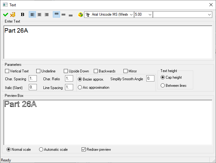
Enter the required text in the upper window of the Text dialog and modify the parameters as necessary. The text is automatically previewed in the lower window. Click OK ![]() when finished.
when finished.
Required Step 2
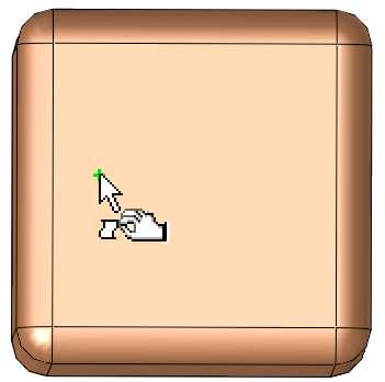
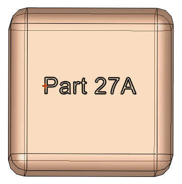
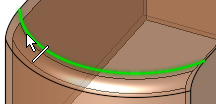
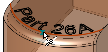
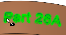
Position the text on the part. You can select any position on a face or a predefined point (to position the text dimensionally).
|
|
|
|
|
Pick the location to |
The text is displayed |
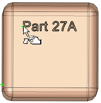
Reposition the text as needed by pickingpicking a different location on the part |
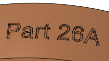
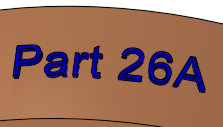
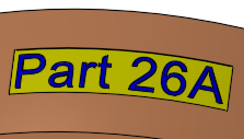
Note that text is displayed in RED in the graphics display area to indicate a problem. For example:
-
If the text does not fit the selected geometry.
ExampleExample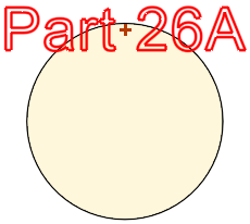
-
If, due to the curvature of the selected geometry and the size of the text, the letters of the text overlap each other.
ExampleExample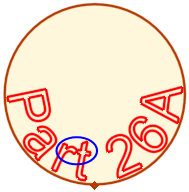
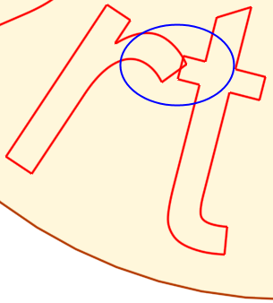
Overlapping text
Set the parameters as required (See the Parameters table below for a list of all the Volume Text parameters and their definitions).
|
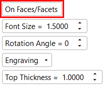
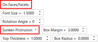
When selecting the On Faces/Facets parameter, the following screen parameters are displayed. |
When selecting the On Faces/Facets and Sunken Protrusion parameters, the following screen parameters are displayed. |
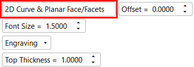
When selecting the 2D Curve & Planar Face/Facets parameter, the following screen parameters are displayed. |
|
|
|
|
Parameters
|
On Faces/Facets / |
Toggle option to define the geometry on which to add the text. Active Component (if the text style option (below) is not set to New Object): If the selected geometry belongs to one object, the active (reference) component is that of the selected geometry. If the selected geometry belongs to more than one object, you are prompted to select the active (reference) component. |
||||||||||||||||||||
|
On Faces/Facets |
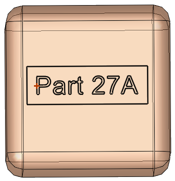
Add the text on faces or facets. Pick a point close to a face or facet; the text is immediately added to the selected geometry. This is the default option.
The point must be on a face or facet. The text anchor point can be dimensioned to an edge or corner to allow exact text placement. |
||||||||||||||||||||
|
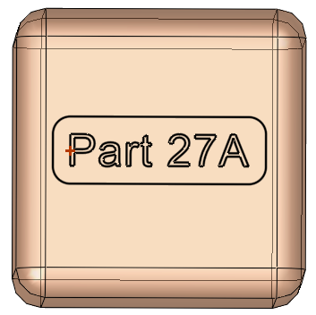
2D Curve & Planar Face/Facets |
Add the text to a planar curve on faces or facets.
When this option is selected an Offset parameter is displayed.
|
||||||||||||||||||||
|
Font Size |
Set the required font size in the text. Default = 5 The font size set in the Text dialog and in this step of this function are identical. Editing the font size in either step updates the size in both steps. |
||||||||||||||||||||
|
Rotation Angle |
Set the rotation angle of the text. See Setting a Text Rotation Angle for further information and examples. This parameter is only displayed for the On Faces/Facets option. |
||||||||||||||||||||
|
Engraving |
This is a dropdown list of the following text display options - see the examples below:
The images below show the differences between the various text display options.
|
||||||||||||||||||||
| Top Thickness |
The height or depth of the text, according to the selected text display option. The images below show the differences in the text height/depth.
Default = 1 mm |

Note: The default preview option is Manual Preview. This shows the text in the selected location on the object, however, the text display results (Engraving, Protrusion, etc.) are only shown after executing the function.
When you have finished defining the parameters, click OK ![]() or Apply
or Apply ![]() in the Feature Guide.
in the Feature Guide.
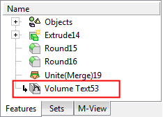
When completed, the Volume Text feature will appear in the Feature Tree.

|