|
|
Progressive Die Setup Wizard 

Access: Invoke this function from one of the following locations:
-
Click the Progressive Die Setup Wizard
button from the initial
toolbar. -
Select Tools > Setup Wizards > Progressive Die Setup Wizard from the initial menu bar.
The Progressive Die Setup Wizard assists you in setting up a new Die file by prompting you to define the appropriate parameters. The die application enables you to set up two different forming shape parts. You can import parts containing other formats, such as DXF, IGES, and more.
The Setup Wizard can be invokedinvoked at any time, whether or not another file is open.
General Interaction
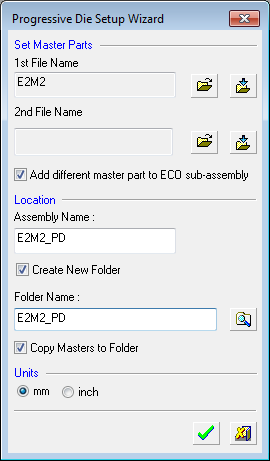
The Progressive Die Setup Wizard dialog is displayed:
-
Define the following parameters:
Use the 1st File Name field to select or import the required die assembly file:
-
Open File
 : Open a Cimatron Part or Assembly file (from the Cimatron Explorer) to create a new Die file.
 -
Import File
 : Import an external file (PFM, IGES, SAT, etc.).
The Assembly Name for the die assembly file is automatically created with a 'PD' (Progressive Die) suffix.
Note: If required, you can select another file using the 2nd File Name field. Cimatron supports all situations where the ECO participants are in different locations.
-
- Mark the Add different master part to ECO sub-assembly checkbox if required.
This option opens a new sub-assembly (ECO) under the main Die Layout assembly and places a copy of the master file used by the work file. (The copied master file will be used later for compare operations.) See the example assembly tree structure at the end of this Help topic. -
In the Folder Name field, either:
-
Accept the default location to save the die assembly file, or
-
Mark the Create New Folder checkbox to activate the Folder Name field.
-
Browse to display the Cimatron Browse For FolderCimatron Browse For Folder window.
-
Click Create New Folder to define the folder name.
-
Click OK.
Note: If you marked the Create New Folder checkbox, the Copy Masters to Folder checkbox becomes available. Optionally, mark this checkbox to add the master part to the project folder, to maintain an organized environment.
-
-
- In the Units area, select mm or inch as the required units of measurement for the die file.
-
Click the appropriate confirmation button:

OK: Accept the changes, perform the operation, and close the current dialog/task.

Cancel: Cancel all changes and close the dialog/task without saving the settings.
When OK is pressed, the following assembly tree structure is displayed (using the data as shown in the dialog above).
Note that the Progressive Die assembly icon is displayed as :
:
The assembly tree structure:
The assembly tree structure when the Add different master part to ECO sub-assembly checkbox is selected (the ECO sub-assembly is created):
Additionally, three parts are automatically created in the Feature Tree by the Progressive Die Setup Wizard. These files provide a framework for a suggested workflow and can be used to create the files required by die block manufacturers. For more, see Optional Workflow.
Notes: Symbolic text can be used for Progressive Dies to help automate common notes on a drawing.
-
Symbolic text parameters for die design data all start with the word Die at the beginning of the parameter name so that they can easily be located in the parameter list.
-
The symbolic text is created as attributes of the main assembly.
-
The symbolic text is saved in the strip part, strip sub-assembly, and also the main assembly.
Optional Workflow Components
The Strip Part in Cimatron is essential for the die design process, especially for progressive dies. It represents the metal sheet used to form parts and includes various forming shapes that dictate how the material will be manipulated during stamping.
The Cimatron Sketcher is used to create the 3d model of the component you require, and then the Die Design module is used to develop the flat shapes that are required to form your design. However, most toolmakers who produce the press dies do not use this file, but will develop separate die cut and punch cut sheets that are used in die manufacture. Delegating this process does not always guarantee an accurate transfer of details and features, and adds an added cost to the die manufacture overhead. By producing your own Die Cut Sheets and Punch Cut Sheets that the Die manufacturer can use to create the dies, you retain control of this part of the process and can ensure your design is accurately reproduced.
At the end of the Die Design process in Cimatron, your final developed part outlines and all of the forming shapes needed to create your design are sheet bodies with no thickness.
The Die Shoes are machined from solid blocks of steel. To create the instructions to manufacture them, you provide the files to cut that block to create the 3D sheet surfaces by extruding the shape to, for example, a square or rectangular block. Typically, die manufacturers require these original sheet surfaces to be sent, along with the 3D die design. They use these sheets for machining if any work needs to be done on the tool.
-
3D strip: The strip layout consists of sheet bodies with no thickness. This includes the Strip Part and all of the Forming Shapes. When the design is finalized, this final strip design can have a thickness applied to it to become a closed solid body. The 3D strip part can be used as the destination to copy the entire strip design and apply a thickness.
-
Die Cut Sheets: The normal starting point when creating a shape is to extrude a square or rectangular block, then to cut that block to the 3D sheet surfaces to transfer the shape to the block. This file contains all the sheet surfaces to do the cutting. The strip design is imported into this folder using the File > Import > Import Geometry command and the block is created. Generally, because there will be a significant amount of work performed in this stage, it is not efficient to maintain the file association with the original.
This folder will hold the design for each station in the progressive strip.
Many tooling firms require the original sheet surfaces be sent along with the 3D die design to enable them to perform any work that needs to be done on the tool. This file holds the sheets for the bottom half of the tool. -
Punch Cut Sheets: The strip design is also imported into this folder and the block for the top half of the tool is created. This folder will hold the design for the top half of each station in the progressive strip.
|