Positioning/Aligning Views
Views can be positioned/aligned very easily. Multiple views can be aligned to a single view. The position of source views can be fixed while derived views are dragged.
Views are aligned automatically or manually. For example, when creating derived views, the views are aligned automatically. A view can then be dragged to another position and, if required, manually aligned with another view.
Manual alignment enables you to drag the views and position them as required.
Note: When dragging views, Preferences enable you to:
-
Limit the aligned view dragging direction
-
Set when to allow views to be dragged – only while editing them or always
View Connection Rules
- Views of the same model are automatically aligned based on their location in the model. Views not of the same model or with other characteristics are center aligned (see Automatic Alignment for additional details).
- Numerous views can be aligned to a single view (see Manual Alignment for additional details).
- Between every 2 views there is only one alignment connection (see Manual Alignment for additional details).
- If a new alignment connection between 2 views is formed, and an older connection already exists, the old connection is removed (see Manual Alignment for additional details).
Multiple Selected Views Dragging Rules
- When picking multiple views for a dragging operation (using Pick By Box, for example), all the selected views are dragged together.
- If a multiple-selected view is restricted in it's movement (due to it's alignment with a parent view) but the parent view was not selected in the multiple pick operation, the alignment between the 2 views is removed and the child view can be moved together with the other multiple selected views.
Automatic Alignment
When creating views (derived views, etc.), the views are automatically aligned. The automatic alignment "rules" are as follows:
|
Views of the same model, are automatically aligned based on their location in the model. |
Views with the following characteristics are automatically center aligned: |
|
|
|
Manual Alignment
Manual alignment enables you to position the views as per your requirements.
- Manual view alignment by dragging
- Manual view alignment by function/option
- Align view horizontally (X) axis
- Align view vertically (Y) axis
- Remove alignment
Dragging a View
Pick a view (or pick multiple views) to drag it to the required position. All drafting entities associated with the picked view (such as Hatch, ID Number, etc.) are also dragged with the view. If the selected view is aligned with another (parent) view, the movement of the selected view is restricted to the axis of the alignment (see the examples below).
In the examples below, there are 3 views: V1, V2, and V3
-
V1 is the original view
-
V2 is derived from V1 and is vertically aligned with it (in the Y axis)
-
V3 is derived from V2 and is horizontally aligned with it (in the X axis)
Note: When dragging views, Preferences enable you to:
-
Limit the aligned view dragging direction
-
Set when to allow views to be dragged – only while editing them or always
For all the explanations, see the examples on the right for clarification.
|
As per the connection rules above, between every 2 views there is only one alignment connection. This means that if V3 is manually dragged, V2 also moves (to keep the X axis alignment with V3). In these examples, V2 can only move vertically (in the Y direction) due to it's alignment with V1. As per the connection rules above, if a new alignment connection between 2 views is formed and an older connection already exists, the old connection is removed. For example, V3 is currently aligned with V2. If V3 is then aligned with V1, the old alignment between V3 and V2 is lost. As per the connection rules above, numerous views can be aligned to a single view. In this example, V1 and V3 are aligned with V2. This means that if V2 is manually dragged, V1 and V3 are also dragged (to keep the alignments). |
V3 is aligned with V2 (in the X axis)
|
If V3 is manually dragged to a new location (for example, vertically in the Y direction as shown below), V2 is also dragged (to keep the horizontal X axis alignment with V3). See below for examples of a Preferences option that limits the aligned view dragging direction. |
|
|
|
|
|
Even though V2 moves to keep it's X axis alignment with V3, V2 can only move vertically (in the Y direction) since it is vertically aligned (Y axis) with V1. If V3 is dragged horizontally (in the X direction as shown below), V2 does not move. |
||
|
|
||
A Preferences option restricts a child view's movements to the direction of the alignment. If this option is activated, this means that (taking the examples above) since V3 is horizontally (X axis) aligned with V2, V3 can only be dragged horizontally (it's movements are restricted only to the X axis – the direction of the alignment with V2). Similarly, V2 can be only dragged vertically (Y axis) due to it's alignment with V1.
Note that if V2 is dragged vertically, V3 also moves vertically with it (to keep the V3 -> V2 alignment).
|
V3's movements are restricted only to the X axis - the direction of it's alignment with V2. |
|
|
|
|
Manual Alignment by Function

Access: Invoke this function from one of the following locations:
Align View Horizontally (X)
-
Click the view to be aligned and select Views > Alignment > Align View Horizontally (X) from the menu bar.
-
Right-click the view to be aligned and select Align View Horizontally (X) from the Graphics area popup menu.
-
Right-click the appropriate view name in the Drawing Tree and select Align View Horizontally (X) from the Drawing Tree popup menu.
Align View Vertically (Y)
-
Click the view to be aligned and select Views > Alignment > Align View Vertically (Y) from the menu bar.
-
Right-click the view to be aligned and select Align View Vertically (Y) from the Graphics area popup menu.
-
Right-click the appropriate view name in the Drawing Tree and select Align View Vertically (Y) from the Drawing Tree popup menu.
Views can be aligned (in the X or Y axis) with any other view.
Note: When manually aligning views, take into account any existing alignment constraints. You may need to manually remove alignments.
Aligning views horizontally (X)
|
|
|
|
|
|
|
Notes:
-
The Undo function is available for all alignment-related operations (Align Symbol Horizontally (X), Align Symbol Vertically (Y), Align View Horizontally (X), Align View Vertically (Y), and Remove View Alignment). If you undo an alignment operation, the aligned entity returns to its original location.
-
An alignment between views can also be removed by pressing the Alt key and dragging the required view to a new location.
-
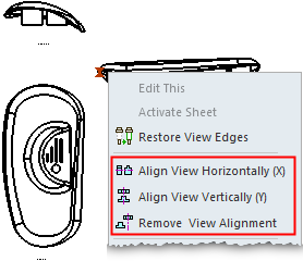
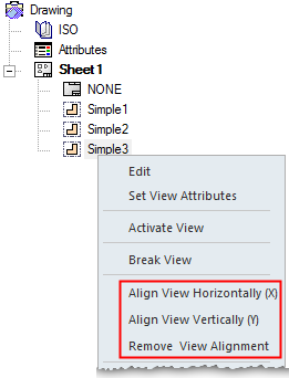
In addition to being available in the Drafting Functions, the alignment-related commands are also available in a popup menu, either by right-clicking a view in the graphics area or by right-clicking a view name in the Drawing Tree as shown below.
Aligning views vertically (Y)
|
|
|
|
|
|
|
Notes:
-
The Undo function is available for all alignment-related operations (Align Symbol Horizontally (X), Align Symbol Vertically (Y), Align View Horizontally (X), Align View Vertically (Y), and Remove View Alignment). If you undo an alignment operation, the aligned entity returns to its original location.
-
An alignment between views can also be removed by pressing the Alt key and dragging the required view to a new location.
-
In addition to being available in the Drafting Functions, the alignment-related commands are also available in a popup menu, either by right-clicking a view in the graphics area or by right-clicking a view name in the Drawing Tree as shown below.
Remove Alignment
Access: Invoke this function from one of the following locations:
-
Click the view to be aligned and select Views > Alignment > Remove View Alignment from the menu bar.
-
Right-click the view to be aligned and select Remove View Alignment from the Graphics area popup menu.
-
Right-click the appropriate view name in the Drawing Tree and select Remove View Alignment from the Drawing Tree popup menu.
-
Remove the alignment between views by pressing the ALT key and dragging the selected view to the required location.
Remove view alignment constraints.
Removing view alignment
|
|
|
|
|
Notes:
-
The Undo function is available for all alignment-related operations (Align Symbol Horizontally (X), Align Symbol Vertically (Y), Align View Horizontally (X), Align View Vertically (Y), and Remove View Alignment). If you undo an alignment operation, the aligned entity returns to its original location.
-
An alignment between views can also be removed by pressing the Alt key and dragging the required view to a new location.
-
In addition to being available in the Drafting Functions, the alignment-related commands are also available in a popup menu, either by right-clicking a view in the graphics area or by right-clicking a view name in the Drawing Tree as shown below.
|
Graphics area |
Drawing Tree |
|
|
|