Contour Manager (NC) > Advanced Contour Selection

Access: Open this function from the following location:
Boundary/Contour selection mode:
Either press the button in the Work
Mode Dialog (if you are in Wizard
Mode), or display the Geometry
parameters in the parameter
tables.
button in the Work
Mode Dialog (if you are in Wizard
Mode), or display the Geometry
parameters in the parameter
tables.
The Geometry Table is displayed:
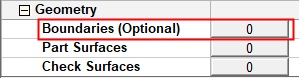
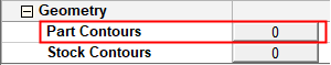
Depending on the current operation, the Boundaries or Contours option is displayed. Press the adjacent button to display the Contour Manager; you are ready to start selecting contours.
See Selecting / Unselecting Geometry.
See the cursor symbols in Cimatron when picking geometry.
Create NC contours from selected geometry.
Additional contour definition parameters are displayed in the graphics window for greater control over the contour creation.
|
Parameters for the selected contour option: |
Contour creation options under the dropdown list: |
|
|
|
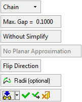
The dropdown selection determines which of the subsequent parameters are displayed.
Parameter display examples:Parameter display examples:
|
|
|
|
|
|
|
|
|
|
|
|
|
|
|
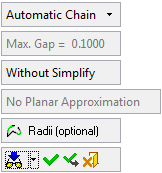
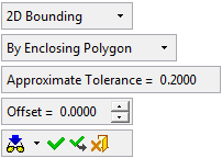
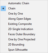
Contour Creation Options
The following contour creation options are available. All these options are available in the Advanced Selection mode, however, some of them are unavailable in the Basic Selection mode.
|
|
|
Parameters
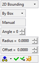
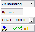
The following screen parameters may appear when using the Advanced Selection mode. The contour creation option that you select (from the top-most screen parameter), determines which of the following parameters are displayed:
|
Chain |
Select the required contour creation option from the dropdown list; see above. |
|||||||||||||||
|
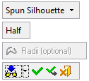
Half / Full |
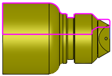
This is a toggle option Half / Full to define the type of Spun silhouette contour to be created from the selected surfaces. The resulting contour is calculated around the Z axis.
This option appears if the Spun Silhouette contour selection method is used. |
|||||||||||||||
|
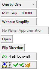
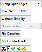
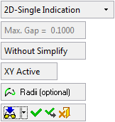
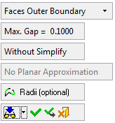
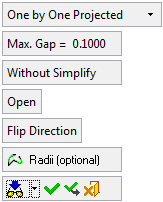
Max. Gap |
This is the maximum gap allowed between the selected geometries, when joining them into a single geometry. If the gap between the selected geometries is greater than the Max. Gap value, they are treated as separate geometries. |
|||||||||||||||
|
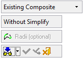
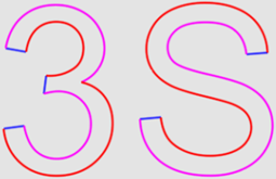
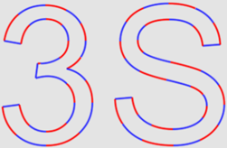
With Simplify / Without Simplify |
This is a toggle option With Simplify /Without Simplify to simplify the resulting contours to allow for a higher quality result with less edges.
|
|||||||||||||||
|
Planar Approximation / No Planar Approximation |
If the contour is not planar, the toggle option Planar Approximation / No Planar Approximation is activated. Planar Approximation allows you to set the contour on the plane (allowing you to perform operations that require 2D input). This option does not appear in the options One by One Projected. |
|||||||||||||||
|
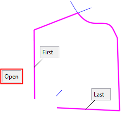
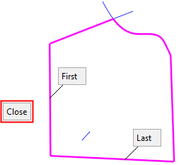
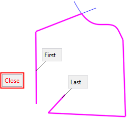
Open / Close |
This option defines the type of curve that is created. This option allows you to close the composite curve automatically or leave it open. If the system cannot close the first and last selected curves/edges when the Close option is selected, the Close option is displayed in red.
This option appears if the One by One or One by One Projected contour selection method is used. |
|||||||||||||||
|
XY Active |
Define the required plane using this toggle option: XY Active / Define Plane.
This option appears if the 2D Single Indication contour selection method is used. |
|||||||||||||||
|
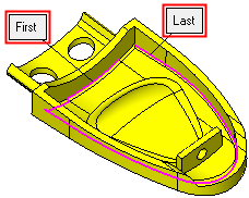
Flip Direction |
Flip the direction between the first and last curve.
|
|||||||||||||||
|
Radii (optional) |
Add or remove a radius, or do nothing, between each of the selected curves. The following parameters are displayed:
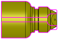
The Radii (optional) button remains in "selected" mode throughout the radius operation. For the different methods of exiting the Radii option, see the Add Radius example below. Add Radius Example:Add Radius Example: In the example below, the pink contour has been selected. If the Add Radius option is pressed, each of the affected corners is marked with a blue circle. Note that the Radii (optional) button remains in "selected" mode.
Set the required Global Radius value for each of the affected corners. The system dynamically shows you the results of the corner radii.
Note: The system creates the radii wherever it is possible. In this example, the requested global radius could only be achieved in two corners. To exit the Radii (optional) option, do one of the following:
Irrespective of which exit option you select, the redefined contour is displayed and the previous contour path is shown in black.
|

When you have selected the required contours, Click the appropriate approval option, which exits the Advanced Selection mode and re-displays the Contour Manager dialog.