Contour Creation Methods
![]()
![]()
Access: Open this function from the following location:
Boundary/Contour selection mode:
Either press the button in the Work
Mode Dialog (if you are in Wizard
Mode), or display the Geometry
parameters in the parameter
tables.
button in the Work
Mode Dialog (if you are in Wizard
Mode), or display the Geometry
parameters in the parameter
tables.
The Geometry Table is displayed:
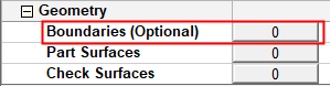
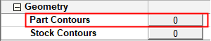
Depending on the current operation, the Boundaries or Contours option is displayed. Press the adjacent button to display the Contour Manager; you are ready to start selecting contours.
See Selecting / Unselecting Geometry.
See the cursor symbols in Cimatron when picking geometry.
NC contours can be created via the Contour Manager by using one of the following methods:
-
Using one of the methods in the Selection Method section of the Contour Manager dialog.
-
Using the Basic Selection mode.
The general contour creation procedure is as explained in Creating Boundaries/Contours.
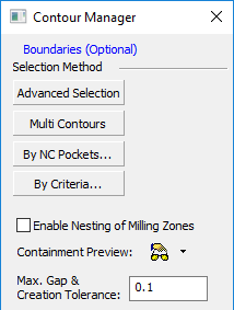
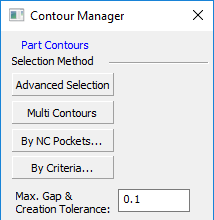
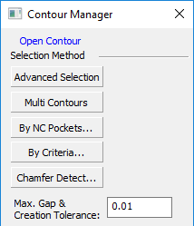
Selection Method section of the Contour Manager dialog
The NC contour creation methods available under the Selection Method section of the Contour Manager dialog, enable you to create contours quickly and also provide a level of automation and control over the type of contour created.
The general contour creation procedure is as explained in Creating Boundaries/Contours.
The following contour creation methods are available under the Selection Method section:
|
Contour selection for Boundaries: |
Contour selection for general contours: |
Contour selection for 2.5X Chamfer procedures: |
|
|
|
|
For more, see:
|
Create NC contours from selected geometry. Additional contour definition parameters are displayed in the graphics window for greater control over the contour creation. |
|
|
Create multiple NC contours from multiple selected curves or the boundaries of selected faces. This option enables the creation of multiple contours from the following entities:
Additional contour definition parameters are displayed in the graphics window for greater control over the contour creation. |
|
|
Create NC contours from previously recognized NC Pockets. The Pocket Selection dialog is displayed. This is similar to the Pocket Manager dialog, however, it is used for selection only and not for recognizing new pockets. The geometry selected (for example, the pocket's volume, surfaces or contours) depends on the active procedure. As when the Pocket Manager is active, the pre-recognized pockets are highlighted in the graphics window. |
|
|
Create NC contours by selecting specific criteria upon which the contour creation is based. The By Criteria creation method is very similar to the Multi Contours method. The only difference is the way the input is gathered:
See Selecting Geometry by Criteria for additional information on the By Criteria method. |
|
|
Automatically detect sharp edges as candidates for chamfering ("Imaginary" chamfers) as well as "Designed" chamfers, based on parameter settings. The detected geometry is then automatically used as input for the chamfering toolpath. The Chamfer Detect option is displayed for the procedures: Chamfer Open Contour and Chamfer Closed Contour. Additional contour definition parameters are displayed in the graphics window for greater control over the contour creation. |
The next two parameters are displayed in the contour selection sessions for the following procedures: Rough Spiral, Rough Parallel, Finish Mill All, Finish Mill by Limit Angle, Finish Horiz. Planar Areas, Cleanup and Pencil. Set the parameters if required:
|
Enable Nesting of Milling Zones |
When checked, this option enables the nesting of milling zones for Rough, Finish, Cleanup and Pencil procedures. The default state is unchecked. This option is also displayed in the Boundary Settings procedure parameter table for the above mentioned procedures. If the option is selected in the procedure parameter table, then it is automatically checked when entering the Contour Manager dialog and vice versa. For additional information on this option, see Enable Nesting of Milling Zones. |
|
Containment Preview |
Set the Manual or Automatic Preview of the user contours in the current procedure, including contour offset conditions. The Containment shows the area that can be covered by the current tool inside defined contours and the machining area (a combination of the user contour and part surfaces). This preview is similar to the Containment Preview from the Preview grid. The default state is Manual Preview. |
Set the following parameter:
|
Max. Gap & Creation Tolerance |
This value is used to analyze the curves and create the NC contours. |
When you have picked a curve, you can right-click to display the popup menu with additional options.
Note: When creating contours by using any of the methods in the Selection Method section of the Contour Manager dialog, the Contour Manager dialog is hidden while you are picking curves and setting the screen parameters.
Basic Selection Mode
In the Basic Selection mode, you can start creating contours by picking curves immediately, without setting additional parameters.
The general contour creation procedure is as explained in Creating Boundaries/Contours.
Note: When creating contours by using the Basic Selection mode, the Contour Manager is displayed in idle mode while you are picking curves.
When you have picked a curve, you can right-click to display the popup menu with additional options.
When you have selected the required contours, press <exit><exit> (or Finish Selection from the popup menu) to accept the contour selection. The Contour Manager shows the results of the selection.