Spline : Options and Results


Access: Open this function from the following location:
-
Select Wireframe > Create Curves > Spline from the menu bar.
Create a spline.
The 2D or 3D NURBS spline can be created using Through Points according to the order picked while adjusting the slopes of both ends of the spline or by using mathematical representations of the spline (Control Points + Slope Factor).
Required Step 1 
-
The following parameters are displayed, depending on the option selected.

Parameters
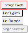
This toggle option enables you to define how the spline is created.
Through Points
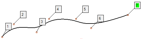
Define the points through which the Spline passes. You can insert new points in the middle of the spline sequence, as shown in this example for inserting new pointsinserting new points.
To insert new points:
-
Pick the point after which to insert a new point (#3). The point is marked in green to signify that it is the last selected point and that any point created after it will be numbered accordingly).
-
Click to insert the new point. The new point becomes #4 and the last point becomes #8.
Demo: Press the button below to view a short movie demonstrating the function:
Practice: Press the button below to open Cimatron with a practice ELT file similar to that used to create the movie (if the relevant feature already exists in the ELT file, you can either edit it or delete it and create a new feature).

Note: The last selected point is always marked in GREEN to signify that any point created after it will be numbered accordingly.
Pick the points through which the spline will pass. Be careful when picking points since the spline will be created according to the order in which you pick the points. You must pick two or more points, and you can unpick points.
ExampleExample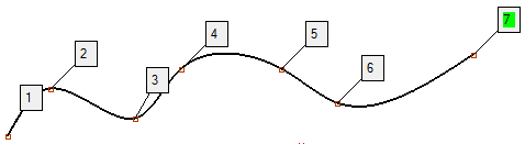
On picking the 3rd point, the Open/Close toggle option appears (see below).
When the Through Points option is selected, the Optional Step 1 available.
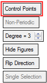
Control Points
Define the exact mathematical representation of the spline using control points with weights.
Demo: Press the button below to view a short movie demonstrating the function:
Practice: Press the button below to open Cimatron with a practice ELT file similar to that used to create the movie (if the relevant feature already exists in the ELT file, you can either edit it or delete it and create a new feature).
Pick the points through which the spline will pass.
On picking the 3rd point, the Open/Close toggle option appears (see below).
When the Control Points option is selected, the Optional Step 2 is available.
This toggle option enables you to create an open or closed spline. Selecting Close creates a Free Slope closed Spline.
This toggle option only appears when the 3rd control point is selected.
Non-Periodic /
PeriodicThis toggle option enables you to define the type of spline required.
ExampleExample
This parameter only appears when the Control Points option is selected.
Degree
Increase or decrease the degrees of the spline. In general, the lower the degree, the closer a B-spline curve follows its control points. The images below use the same control points: One image shows a low degree value and the other shows a higher degree value. As the degree decreases, the generated B-spline curve moves closer to its control points.
See the notes regarding degrees and weights in Optional Step 2 below.
This parameter only appears when the Control Points option is selected.
This toggle option enables you to show or hide the control point numbers.
Flip Direction
Click the Flip Direction button to flip the slope direction.

Single Selection / Select Multi Points
This toggle option enables you to either select single point or multiple points for the spline creation. This toggle option becomes available if at least one point entity is selected (not a geometric point such as end or center).
Single Selection
Select single points for the spline creation.
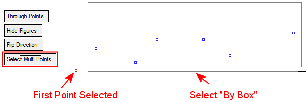
Select Multi Points
Select multiple points for the spline creation using the By Box option. The selection order of the points is according to the distance from LAST point in the chain.
-
Optional Step 1 
-
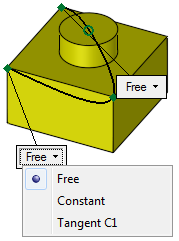
If Through Points is selected in Required Step 1, set the slope for one or both ends.
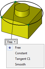
By default, the ends have Free slopes. To modify the slope at the end of the spline, click the Free parameter and select one of the Slope options from the dropdown list.
The Smooth option is only displayed if the options Through Points and Close were used.
Note: Splines created from 3 points, or from two points and fixed slopes, will be created as arcs.
Slope options
Free
The slopes are created freely at the ends of the spline.
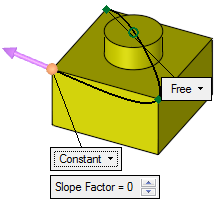
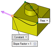
Constant
Allows you to define a Slope Factor which sets a value to control the normal of the spline to the point. The Slope Factor is a value from 0 to 10, with a default of 5 and determines how much the vector line is stretched. A zero value has no effect on the slope.
A directional arrow also appears. You can either flip the direction by clicking on the arrow or click on the arrow origin point to set a direction.
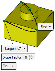
Tangent C1
Allows you to define a Slope Factor which sets a value that controls how much the line adheres to the tangent before forming the spline. The Slope Factor is a value from 0 to 10, with a default of 5 and determines how much the vector line is stretched. A zero value has no effect on the slope.
A Flip button is displayed. You can either flip the direction by clicking on the arrow, or click on the arrow origin point to set a direction.
The example below shows how Slope Factor effects the Tangent C1 parameter.
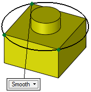
Smooth
Create a smooth spline. This option is only displayed if the options Through Points and Close were used.
Examples
Constant
Set a slope factor and a direction.Tangent C1
Set a slope factor.
Flip if required.Smooth
Optional Step 2 
-
Set the weight of specific control points. Increasing the weight of a control point pulls the spline towards that point. This option is only available if the Control Points option is selected in the required step 1.
Notes:
-
If all the control points have the same weight, the geometry is always identical (it does not depend on the global weight value).
-
The curve always starts in the first point and ends in the last point (it does not depend on the degree and weight values).
-
If you change the weight of a single point, the system takes into account the weight of the adjacent points. The number of neighboring points taken into account depends on the degree of the spline (the degree is set in Required Step 1 above). For example, for Degree=3 the weight of three points in each direction are taken into account (3 points right and 3 points left of the point whose weight value was changed).
-
If the weight is more than the weight at neighboring points, the curve passes close to this point. If the weight is less than the weight at neighboring points, the curve passes further from the point.
Pick the points to be used as control points and enter their weight value
Modify the Spline weight values accordingly
The result
-
-
Click OKOK
 or ApplyApply
 in the Feature Guide to complete the function.
When completed, the Spline feature will appear in the Feature Tree.