Common Parameters for all machines
In this section it is described each one of the parameters common for all the technologies. These tables appear when you press on a process icon, once the part is already defined.
-
Constant Conic and Variable Conic
-
Pocket
- Main Tab for all technologies
- Access Tab
- Cut Tab
- Corners Tab
Constant Conic and Variable Conic


The tables for the constant conic and variable conic processes are:
-
Main tab
-
Access tab
Access parameters explanation Start from thread point Return to thread point Perpendicular exit (only 4X) Final Pocket -
Cut tab
End stop point distance Path Type Phase number Overlap Wire Thread Wire cut Direction for remnant calculation Compensation Calculate pocketing areas Initial Stop Final Stop Entry / Exit Technology -
Corners tab

The parameters for the “Pocket” cycle are:
-
Main tab
Comment Wire Diameter Cut Width Finishing offset Side Step Drill Diameter Angle Final skim distance Final Step Nr -
Cut Tab
ATTENTION
The values that you set in the technology tables for wire diameter, offsets, etc., are only relevant for simulation and will not be reflected in the numerical control program. However, it is very important to set the same parameters for the simulation that you would set for the actual machining, as this way you will know if there are undercuts, interference, etc. before sending the program to the CNC machine.
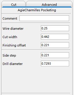
Main Tab for all technologies
-
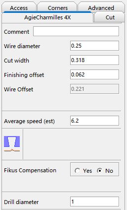
Comment
Optional field. Enter a work-related comment. You are limited to 50 alphanumeric characters. When you postprocess, the comment will appear at the beginning of the program.
-
Wire Diameter
This is the value of the physical diameter of the wire (in system units) that you are going to use in your work.
-
Cut width
Real cut width (in system units) by the wire. It equals to the wire’s diameter + 2 times the gap (spark). It will depend on the cut condition.
-
Finishing offset
Distance (in system units) that must exist between the end of the cut to the selected geometry. It is equal to the finishing margin.
This is a parameter that will only affect the simulation.
-
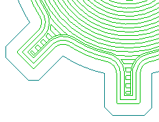
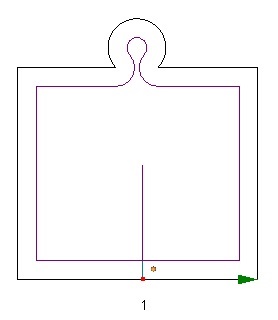
Side step (only for Pocket process)
The step between each wire movement. You can see an example in the following picture.
-
Drill Diameter (only for Pocket cycle)
You can specify the diameter of the inner island of the pocketing.
-
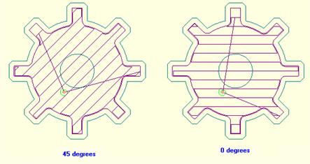
Angle (only for Pocket cycle – linear cut)
You can force the wire movement to follow a defined angle. It is only effective if you choose Linear Cut.
-
Final skim distance (only for Pocket process)
You can set a Final skim distance to achieve the best machining accuracy. The wire will do a final skimming of the part to eliminate this extra offset.
-
Final Step Nr
The number of skimming steps that the pocketing toolpath is going to do to the part.
1 Step 3 Steps 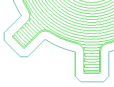
-
Gouge Checking Y/N
The Gouge Check allows Cimatron to modify the geometry in order to avoid compensation problems.
The default option is to activate the gouge checking,
 . If you don't want to apply it press the icon and the image
 will be shown.
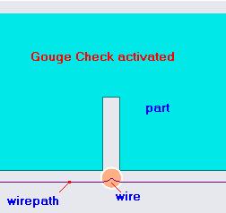
Cimatron will check the geometry and will redefine it (in an internal way) solving the critical areas.
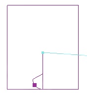
See also the next pictures to understand this powerful function.
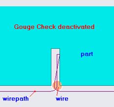
In the first picture the command is not checked and the next error message will appear:

This is the solution that is given by the system if you keep the Gouge Check option activated and the message that you’ll get:

-
Cimatron Compensation
By answering Yes / No you define if the calculated toolpath will be postprocessed instead of the geometry or not, that's if is Cimatron or the machine who does the compensation.
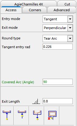
Access Tab
Access parameters explanation: defining the access
There are basically 6 types of access motion and can be combined in the entry and exit motions:
-
Perpendicular
This is a two movements entry / exit.
In this case you will have to define the Entry / Exit Length, which refers to the perpendicular part of the access.
The second movement is the result of returning to the thread point (if selected). -
Tangent Tear Arc
This is a two movements entry / exit.
In this case you will have to select Tear Arc as Round Type and define:
1. Tangent Entry / Exit rad:value (in system units) of the rounding radius. 2. Covered Arc (Angle):arc covered by the radius.
The second movement is the result of returning to the thread point (if selected). -
Tangent Semicircle
This is a two movements entry / exit.
In this case you will have to select Semicircle as Round Type and define the Tangent Entry / Exit rad, which is the value (in system units) of the rounding radius.
The covered arc is always 180 degrees.
The second movement is the result of returning to the thread point (if selected). -
Tangent Bullet
This is a three movements entry / exit.
In this case you will have to select Bullet as Round Type and define:
1. Tangent Entry / Exit rad:value (in system units) of the rounding radius.
2. Covered Arc (Angle):arc covered by the radius.
The second movement goes parallel to the original defined entry / exit motion until the threading level point is reached.
The third movement is the result of returning to the thread point (if selected). -
Tangent Bell
This is a three movements entry / exit.
In this case you will have to select Bell as Round Type and define:
1. Tangent Entry / Exit rad:value (in system units) of the rounding radius.
2. Entry / Exit drop length:length over the original entry / exit motion which defines the final point for the second movement (line from the end of the arc).
3. Covered Arc (Angle):arc covered by the radius.
The third movement is the result of returning to the thread point (if selected). -
Free
This is the original entry / exit motion defined by the user.
Options over the threading point and the final pocket
-
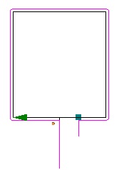
Return to thread point Y/N


This function indicates if the machine will return at the end process to the threading point
-
Start from thread point Y/N


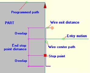
This function indicates if the machine will start from the threading poing. If this option is unchecked a small entry motion, using the wire exit distance, will be done instead of the defined entry motion.
-
Perpendicular exit Y/N


On a 4X process you can choose between a UV perpendicular exit or a UV exit as a XY exit motion projection. This exit applies only to exit motions to wire exit distance, not exit motions to thread point.
Without perpendicular exit With perpendicular exit 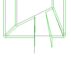
-
Final pocket Y/N


This function indicates if the machine will make a small pocket in order to clear the region to avoid the contact of the wire
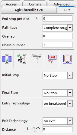
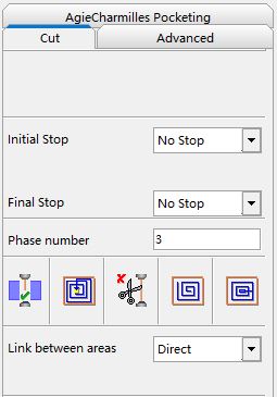
Cut Tab
-
End stop point distance (remnant)
Distance (in drawing units) with respect to the initial entry motion in which you want the machine to stop cutting, i.e. where you want the machine to stop so that you can clamp the part, etc.
You can define it by distance or by percentage over the contour length .
-
Path type
You can perform 6 different path types to optimize your work. Press on
 to display the various options. The following options are available:
 -
Phase number
A phase number can be defined. By default, in the Toolpath Manager tree, the processes inside each toolpath are sorted by geometry. To sort by phases, press on
 and the
processes will be sorted depending on the phase number that you
have assigned to each of them.
and the
processes will be sorted depending on the phase number that you
have assigned to each of them.This option is very useful. For example, you can machine all the geometries overnight (until the remnant), and in the morning just do the Remnant Cut and Remnant Skimming.
See section How to order by phases/ by geometry
-
Overlap
Distance (in drawing units) that the wire will be above the machining start and end points (entry motion and stop point), to obtain optimum machining quality and to avoid marking the machining start and end points.
This option cannot be activated for until remnant processes.
Below you can see an example of using an overlap on a Remnant Skimming process
-
Wire Thread Y/N


This function indicates if the machine has to thread the wire at the beginning of the process.
Wire electrode: M06
-
Wire Cut Y/N


This function indicates if the machine has to cut the wire at the end of the process.
Cutting of wire electrode: M07
-
Retract Y/N (only for Pocket process)


The retract option will force the last wire movement to go to the start machining point.
-
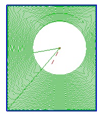
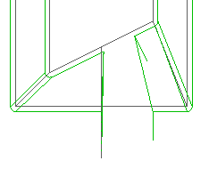
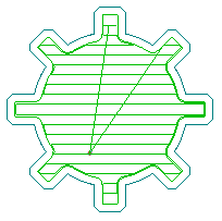
Linear/Spiral Cut


You can choose between two different cut movements: spiral and linear cut. You can see the difference in the following picture:
Spiral Pocket Linear Pocket 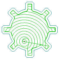
-
Average Speed (estimated)
Average speed for the XY Feed. In system units. When the process is calculated, the estimated time is shown when placing the mouse cursor on the process
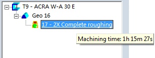
The total time for a geometry is shown placing the mouse cursor on the geometry. The total time for a wirepath is shown placing the mouse on the wirepath icon on the wirepath manager.
-
Direction for remnant calculation


By using this parameter, and in case of having an non-null remnant value, you define which part of the contour will be considered for remnant distance calculation.
Left of the entry motion Right of the entry motion 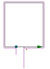
-
Compensation R/L (G40, G41, G42)
G40: programmed contour
G41: left compensation,

G42: right compensation,

By using this parameter you define the side (with respect to the programmed contour) by which you want the center of the wire to move when it is cutting.
-
Calculate pocketing areas Y / N


By using this parameter you decide on machining remnant areas as pocketing or not.
If yes, Cimatron compensation will be used for postprocessing.
Calculating pocketing areas Not calculating pocketing areas 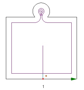
-
Initial / Final Stop
You can insert a stop, before doing any movement, to the start or end of the process.
Two stop types can be defined:
Stop (M00)
The machine is automatically stopped. Machining power supply, wire feed, dielectric fluid supply, and wire tension automatically turn off. Cutting is started again by pressing the start key.
Stop (M01)
Decide whether to turn on the optional program stop switch. -
Entry / Exit Technology
This functionality is only available for some machine models.
You can decide whether to change the technology or not.
In case of change of technology, you can also decide where: at the access or at the contour (in both cases the distance has to be specified), or on breakpoint (next or previous point to the threading point)
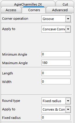
Corners Tab
This tab is divided in two main areas.
These operations are not independent absolutely. We can do nothing, only one or both; but in this last case the operation corners is executed at first and thus the round or sharp corners operation affects the geometry modified by first.
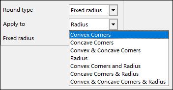
Modifications to do on elements
The default option is do nothing. In order to be able to see the parameters that define an operation it's necessary to select first what operation is wanted to be done.
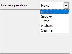
Once the kind of operation isselected, the type of element which we want to apply the modification on has to be selected.
These elements type can be divided in:
- Corner elements (inner and outer)
- Radius elements (only inner)
- Corner technological point elements
The options shown are all the possible combinations between them.
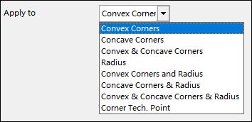
This pull down is common to all the options.
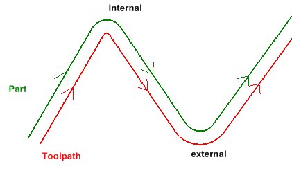
To be an internal or external element is going to depend on if are treating punch or die, on the toolpath position respect to the part and on certain ranges.
-
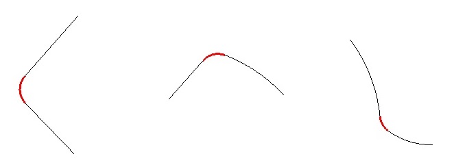
Corner elements: Inner Corners / Outer Corners
Every vertex in which its adjacent elements have a tangential discontinuity will be considered as a corner (lines or/and arcs).
In case of the adjacent elements are arcs, we will use the tangent lines for calculations, constructions, etc; but the resultant geometry will always be over the original geometry.
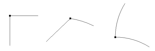
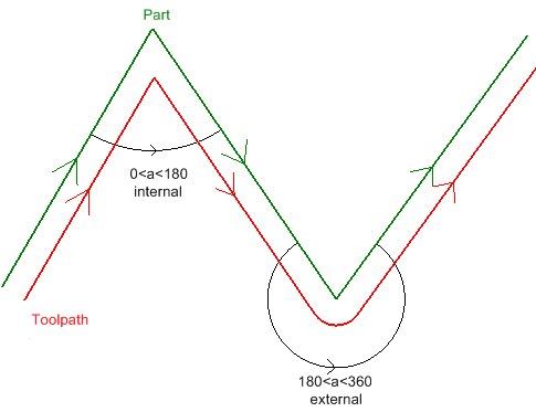
A corner will be considered as inner if the pitch angle (regarding to the toolpath) between a side of the corner and the other is between 0� and 180�; and outer when it is between 180� and 360�.
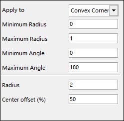
We can limit the operation application range over an element. If we select any option related to corners, "Minimum angle" and "Maximum angle" fields are shown. The default range is 0 for the minimum angle and 180 for the maximum angle, and they are also the limit values.
In case of inner corners the range is defined by these values. For the outer ones is the resultant range of adding 180� to each extrem.
For instance, a minimum angle of 30� and a maximum of 60� mean:
- Inner corners: the selected operation will be applied on every corner whose pitch angle is between 30� and 60�
- Outer corners: the selected operation will be applied on every corner whose pitch angle is between 180�+30� and 180�+60�, i.e. between 210� and 240�.
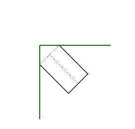
For the inner corners, the figure is built "towars the outside" of the corner; in case of outer ones, "towars inside".
Outside Figure Inside Figure 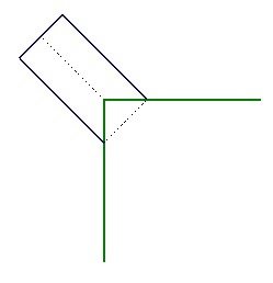
-
Radius
An arc will be considered as Radius if it is the result of rounding an inner corner (between 0� and 180�, arcs or/and lines cases).
We can limit the operation application range over those arcs depending on their radius. If we select any option related to radius, "Minimum radius" and "Maximum radius" fields are shown.
-
Corner technological point elements
These are the points defined as corners technological points.
In this case the operation only be done over this punctual elements regardless of the corner type. No range will be considered .
After these range parameters we have the own parameters of the geometric figure to apply.
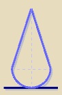
Let we see them graphically one by one in the case of outside figure (the case of the inside ones is symmetrical):
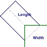
| Groove |
Length is not the groove height, is the distance from the vertex from the corner to the rectangle upper base. |
|
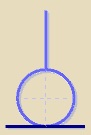
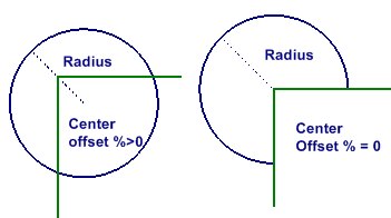
| Circle |
When there is a value of center offset the circle center will be moved along the bisector of the corner the distance that results of applying the percentage value over the radius. |
|
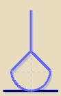
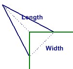
| V-Shape |
Length is not the v-shape height, is the distance from the vertex from the corner to the opposed vertex of the triangle. |
|
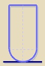
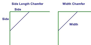
| Chamfer |
We have two ways to define a squared chamfer, by the side length over the figure and by its own chamfer width. |
|
These values will be real dimensions on initial geometry. When mechanizing the toolpath will be shown, but the geometric operation is done on the original geometry, and then the toolpath is calculated with this modified geometry. See the next example (applied on inner corner and radius):
|
|
|
Round and Recover sharp corners operations
-
Rounds between non tangent elements or modifying one existent round
- This case corresponds to the firts two options, Minimum radius / Fixed Radius. The user must indicate the radius to use for the last one.
-
Element type which we can apply the modification on are the same as in corner operation but the special technological point.
In case of non tangent element, It must'n be necessarily two straight lines, is enough if there is no tangential continuity between elements.
Inner radius are the existant round that can be modified.
-
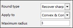
Recovery of sharp corners in radius
- This corresponds to the last option.
-
It can only be applied on radius (inner ones, those which are an inner corner round and / or outer ones, outer corners rounds).
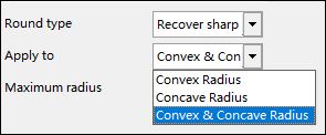
- If Maximum radius field is 0, the operation will be applied on all the selected type rounds. In case of being greater than 0, on all the selected type rounds with a radius less or equal to this value.
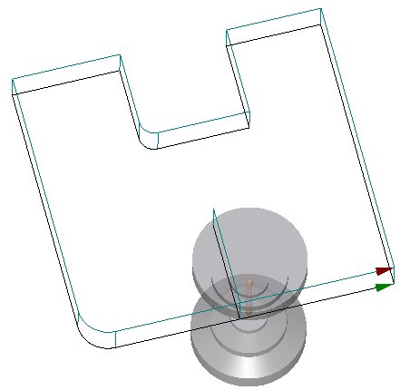
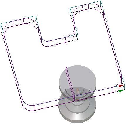
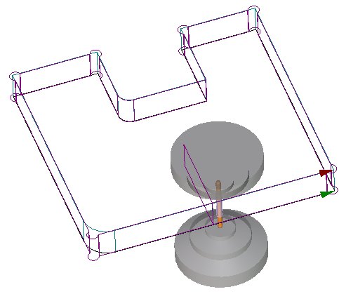
Let's see an example:
| Conditions | original geometry | toolpath result |
|
|
|
|