|
|
2D Bounding  : Options and Results


Access: Open this function from the following location:
-
Select Wireframe > Derived Curves > 2D Bounding from the menu bar.
Create a 2D (projected) Bounding Box contour around selected entities. Pick one or more 2D contours and the system finds the tightest square, circle, or enclosing polygon that completely surrounds the selected contour(s).
Required Step 1 
-
Click to pick the entities to be bounded and <exit><exit>.
Required Step 2 
-
Set the parameters and change the projected plane if required. This function is also used in the NC environment where the result is an NC contour which doesn't appear in the CAD Feature Tree.
The following parameters are displayed alongside a preview of the bounding box;
2D Bounding parameters in CAD
2D Bounding parameters in NC
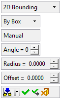
Parameters
By Box
This is a dropdown list that enables you to define how the picked entities are to be bounded. The following options are available:
- By Box
- By Circle
- By Enclosing Polygon
By Box
By Circle
By Enclosing Polygon
Wire Without UCS
This is a dropdown list that enables you to decide how the bounding box is to be displayed. The following options are available:
- Wire Without UCS
- Wire With UCS
- Wire With Points
- Only UCS.
Wire Without UCS
Display a wire bounding entity.Wire With UCS
Display a wire bounding entity, together with a UCS in the middle.Wire With Points
Display a wire bounding entity, together with a point in the middle.Only UCS
Do not display the bounding entity; display only a UCS in the middle.
Note: When the UCS options are selected (Wire With UCS or Only UCS):
-
The UCS is created on the projected plane (you can change the projected plane if required), while the Z direction of the UCS is normal to the plane and the X-Y directions are defined according to the active UCS.
-
The UCS is created as follows:
-
In the By Box option:
The UCS is created in the middle (X and Y parallel to the box lines). -
In the By Circle option:
The UCS is created in the center. -
In the By Enclosing Polygon option:
The UCS is created in the middle of the "box" (X and Y according to the active UCS projected on the plane).
-
Manual /
AutoThis toggle option is only displayed if the By Box method is used. This option enables you to define the size and orientation of the bounding entity. The toggle options are Manual and Auto:
Manual
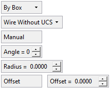
The Manual option gives you control over the shape/orientation of the bounding entity. When this option is used, the Angle and Radius parameters are available.
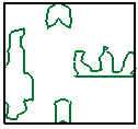
ExampleExampleThe two green entities are selected to be bounded. Note that the Angle and Radius parameters are available.
Auto
The Auto option automatically finds the angle which creates the smallest bounding entity. When this option is used, the Angle and Radius parameters are grayed out and are not available.
ExampleExampleThe two green entities are selected to be bounded. The system automatically selects the angle to produce the smallest bounding entity. Note that the Angle and Radius parameters are grayed out.
Angle
This parameter is only displayed if the By Box method is used and enables you to define the orientation of the bounding box.
ExampleExample
Radius
This parameter is only displayed if the By Box method is used and enables you to define the radius of the bounding box corners.
ExampleExample
Approximate Tolerance
This parameter is only displayed if the By Enclosing Polygon method is used and enables you to define if the result (lines) are approximate to line and arcs and the specific tolerance.
Offset /
Define ValueThis parameter enables you to set the size of the bounding entity, either by defining an offset value or by setting the width, height, or diameter of the bounding entity:
- In the By Box option:
The Offset option can be toggled to Define Value, enabling you to set the Width and Height of the bounding box.
ExampleExampleOffset
Define Value
- In the By Circle option:
The Offset option can be toggled to Define Value, enabling you to set the Diameter of the bounding circle.
ExampleExampleOffset
Define Value
- In the By Enclosing Polygon option:
Only Offset is available.
ExampleExample
Offset values can be positive, zero, or negative.
-
Click OKOK
 or ApplyApply
 in the Feature Guide to complete the function.
When completed, the 2D Bounding feature will appear in the Feature Tree.

|