|
|
Add From Catalog 


Access: Open this function from one of the following locations:
Add a component from the Catalog to the assembly / sub-assembly.
Important: The added component will be assigned to the activated assembly. Ensure that the required assembly is activated before using this operation.
Notes:
-
The creation of duplicate components can be avoided. When adding a catalog component for which there is a similar single part in the assembly, the system will offer to use the existing part.
-
For the Assembly Add operations (Add Component, Add Duplicate, Add This Component, Add External Catalog Part, Add From Catalog, Add New Part, and Add New Sub-Assembly), the following is relevant:
-
-
In the Feature Tree, in addition to the feature name indicating the type of operation performed, the part name of the added component is also displayed in the feature name.
-
The feature created by the Add operation is listed in the Feature Tree under the Add Operations branch of the relevant assembly.
-
In addition to the usual method of editing a feature, this Add operation can also be edited using the Edit Add function.
-
When adding multiple instances to an assembly using an Add operation, the Feature Tree shows only one combined cut operation. The individual cut operations for each component can be viewed under the leaf for the combined cut operation in the tree. The Add operation can also be edited directly from the Feature Tree of the part that was cut, rather than from the Assembly Tree.
ExamplesExamplesNote the one combined cut operation feature at the end of tree.
When expanded, you can edit each cut operation separately.
You can also re-enter the Edit Add operation by editing the combined cut feature.
-
The component(s) is added with the same units as those of the main assembly.
-
General Interaction
This image shows the Feature Guide for Add From Catalog.
|
|
|
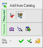
Required Step 1 ![]()
Select a catalog component from the Cimatron Explorer.
Required Step 2 ![]()
Place the selected component using one of the placing options.
Optional Step 1 ![]()
Set the offset and rotation positioning parameters.
Optional Step 2 ![]()
Select a UCS from the added part to position the component.
Optional Step 3 ![]()
The Cut Manager is displayed; select the parts to be cut.
Detailed Interaction
See Options and Results.
|